Abstract
A multi-band radio antenna for the radio amatuer service covering the six ,ten and twelve meter bands.
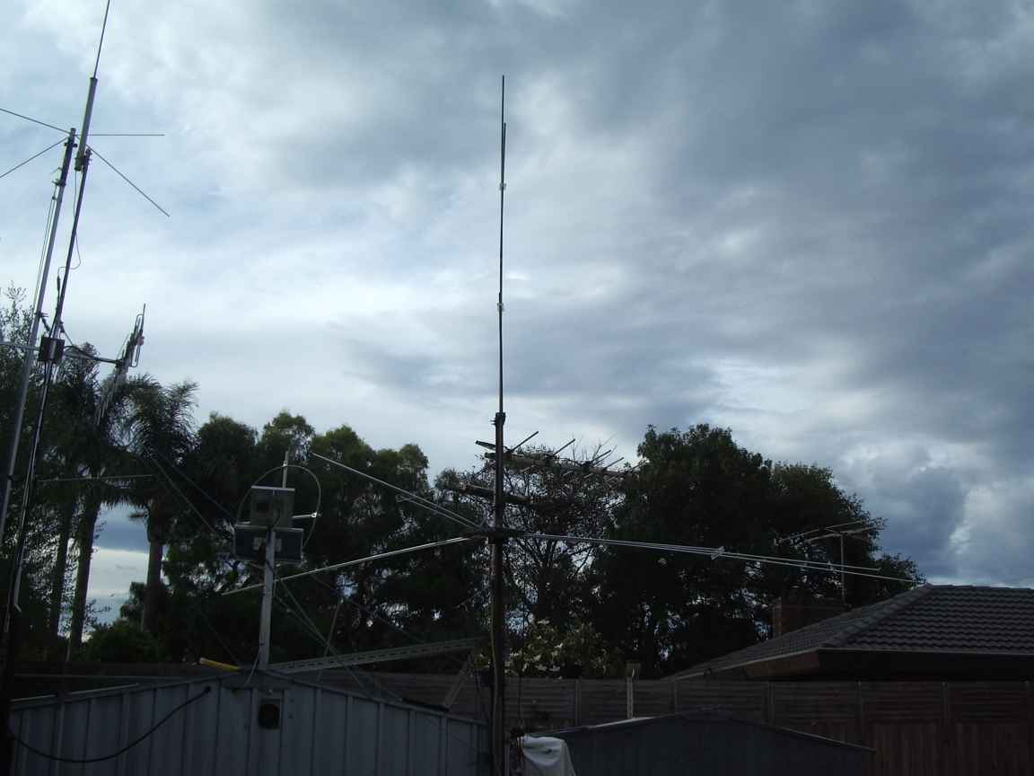
A (possibly world first) implementation of a multi-band vertical antenna based on the classical groundplane antenna. Three non harmonically related radio amatuer bands are covered in the one physical structure.
this article and the antenna design is copyleft. You are free to do with this as you see fit, for all honorable purposes.
Introduction.
The multi band fan diplole is an old idea. Many multiple bands may be covered in the one structure provided that there is no simple harmonic relationship between the elements. They work on the simple principle that the admitance of a quarter wave radiator is extremely low, effectively a short circuit. The quarter wave radiator when energised at its resonant wavelength "deprives" adjacent non harmonically related elements of RF current, and for all intents and purposes adjacent elements are "not there".
Virtual experiments with mininec reveal that adjacent elements do cause a measure of mistuning, however the effect is sensibly small.
Does the concepts in the horizontal fan array multi band dipole translate to a classical ground plane antenna ?
The literature suggests that for some reason no one has bothered to either ask this question of perform the simple experiment.
Some quick modelling with mininec2 quickly revealed that is was possible to make what is similar to an array of organ pipes, each cut for its characteristic wavelength, provided that the radiators had no simple harmonic relationship.
In this case, it is posssible to cut the elements of a groundplane array for 6,10 and 12 meters. The mininec2 impedance graphs shows usefull values of feed impedance at the design wavelengths. The radiation patterns still look like classical groundplanes, but with extra sidelobes, as one might expect. This is not an undesireable feature for an antenna that is meant to be omnidirectional.
Motivation for this project.
I wanted a simple antenna for operation on Six Meters after aquiring a six meter rig at a hamfest. I have never heard much Ten Meter activity, there is such a thing but my large vertical and longwire completely fail to pick up any signals on Ten. The new WARC 12 Meter band appears to be utterly dead on my other antennas. I think it would be nice to generate extra activity on this band even if its just an CW automaton. I was not going to erect seperate structures for each band. If the idea was successful then a more ambitious array could be contemplated for the 20,17,15 meter bands.
Construction and operation.
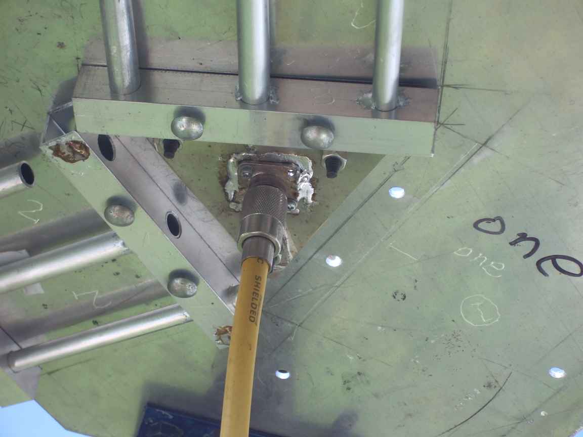
The implementation was driven by the need to make the impedance between the driven elements as small as possible, to ensure , by the model, that the resonant exited element "robs" nearby elements of current at the feed point. The parallel elements thus require true metalurgical bonds achieved by low temperature brazing. The horizontal elements are aluminium, brazed to their supporting structures. The vertical elements are copper, selected for its eaze of reliable weather proof electrical connection and because I had the copper in stock at zero cost. I also wanted to see if there was any operational benefit in using copper driven elements given its significantly lower ohmic resistance. Do not attempt this method if your cannot braze or mig weld aluminium, a pressure bond is not good enough !
As one would expect, this antenna for reception purposes has unusually large bandwidth and at the design wavelengths presents the band noise on frequencies on which I have never heard it before. For casual shortwave listening it has a usefull bandwidth from 20 to 30Mhz.
What was acheived ?
I could key the melbourne VK3RHF 6 meter repeater, never before possible at my qth
I could hear the 10 meter IPB beacons on 28.200Mhz, never before possible at my qth
I could hear North American amatuers on 24.90Mhz, I have never before heard anything on 12 Meters !
I could hear Indonesian CB operators about 27.027 Mhz , I have never heard anything like it !
How extendable is this concept ? Just how many pipes could be done ? Is a continuous wave groundplane structure possible for Ultra Wideband applications ?
Hello again...its 2015 !
And now, after a gap of a couple of years a postscript. There is almost zero activity on 6 Meters in victoria despite many 6 meter repeaters that clubs have gone to the time , effort and expense to provide. There is almost no activity on 6 Meter SSB, allthough the
John Moyle and RD contest do bring out a few feint CQs. There is even less 6M activity that can be recieved with a vertically polarised antenna. The only merit of this design for 6 Meters is a simple feed point arrangement for a truly multiband antenna. Being a 1/4wave ground-plane it suffers from all the limitations of one, principally that it is a high angle radiator, good for a rare tropospheric duct but otherwise useless. If the 6M activity in Melbourne was so warranted I would go to the trouble of creating a proper low angle radiator like a 5/8 vertical. However, I am somewhat pleased with its performance on 12Meters and 10Meters and has provided for a small number of interstate QSOs on 10M and the potential of international 12M contacts on CW, wailing and gnashing of teeth...but my CW skills are not up to the task ! There is zero phone/ssb activity on 12M. I am designing a multi-band yagi for 6,10,12 which will be horizontally polarised and will hopefully fit into the same space as the Organ Pipes. It has shown to me the surprising nature of the 10 and 12 meter bands when the ionosphere so permits and would encourage more hams to create a pressence here. The lesson learned is
that a custom 10M/12M horizontal antenna is absolutely required. A G5RV or piece of wet string does not cut the mustard. The potential for TV interferrence is now eliminated due to digital TV. I can watch my digital idiot box in the shack while transmitting on 10M. This was not possible just a few years ago.
I will still declare the Organ Pipes project a success, but only inasmuch as its' demonstration of genuine multi-band capability, but it clearly suffers from all the same drawbacks as a 1/4 wave groundplane. My advice, do not reproduce.
This antenna is scheduled for removal and replacement with a collection of purpose made horizontal dipoles for 10 and 12 meter bands. A 3 element yagi will also be created. The organ pipes was a successfull experiment but 1/4wave groundplanes send most of the radiation into the sky at a high lauch angle. This would make it a competant antenna for LEO satellites ! but nearly useless for terrestrial applications.
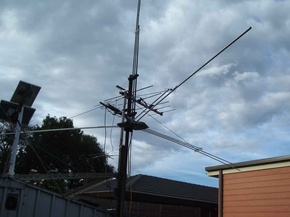
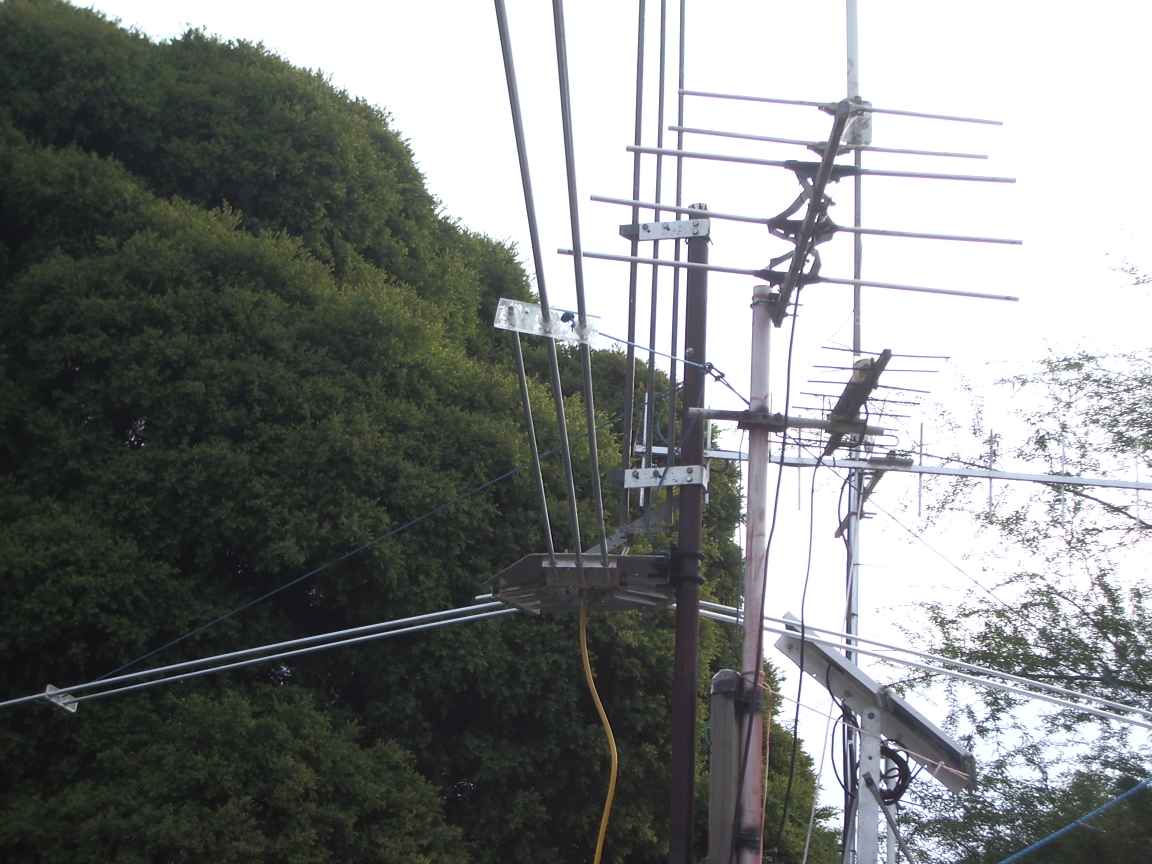
The Organ Pipes Groundplane Antenna array
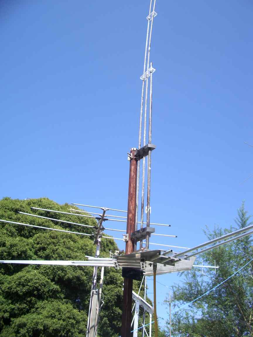
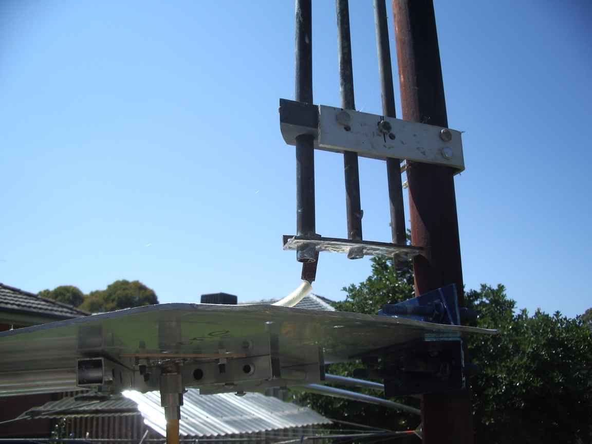
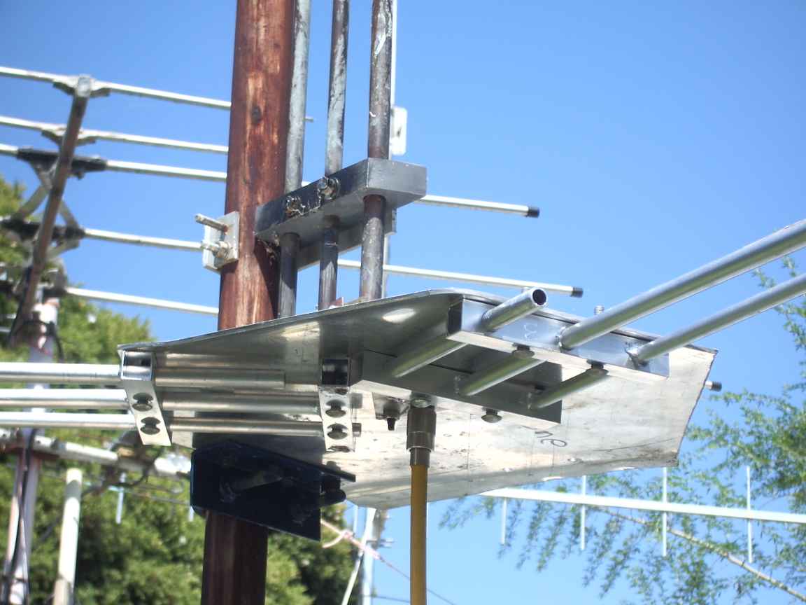
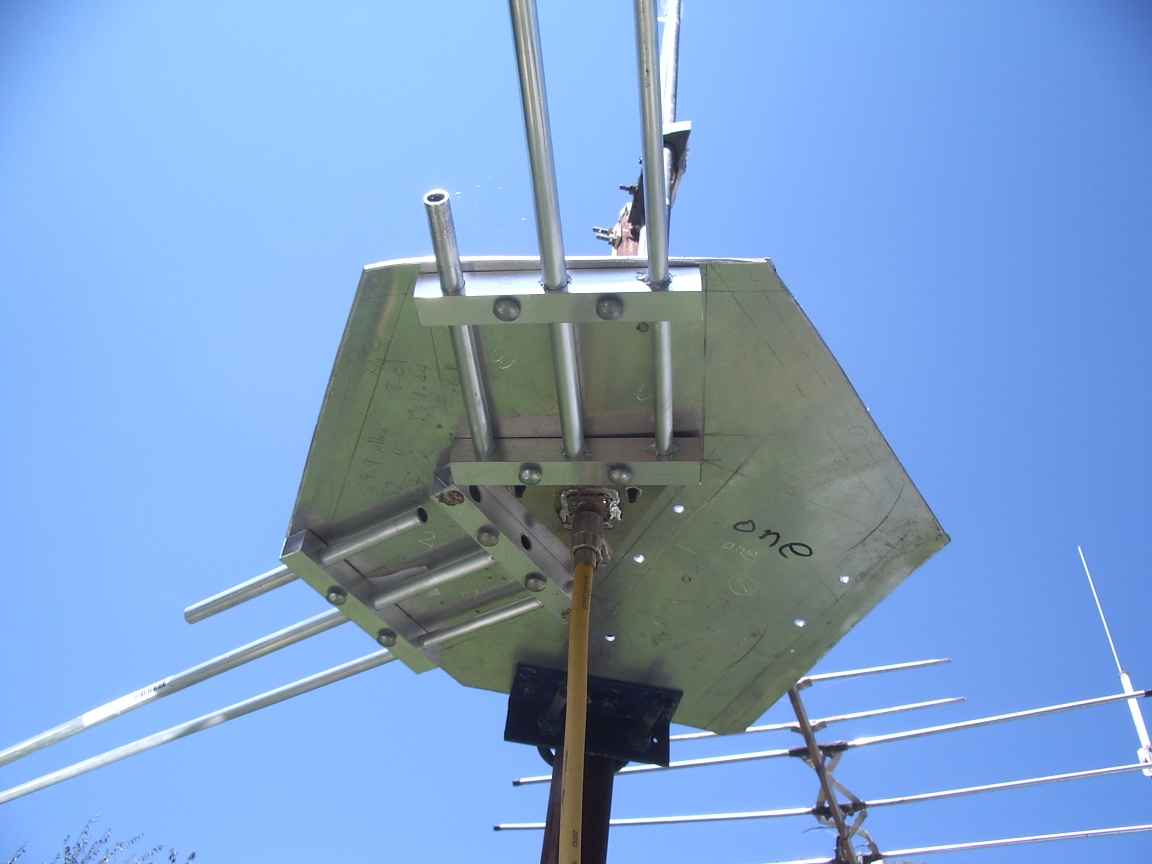
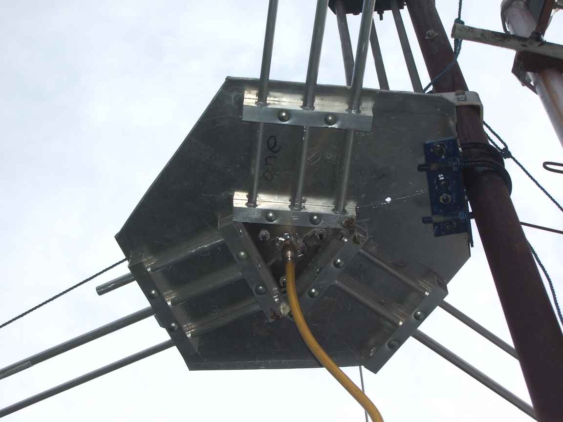

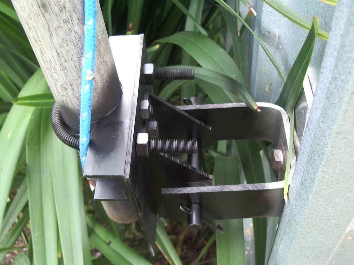
U Bolt bending machine
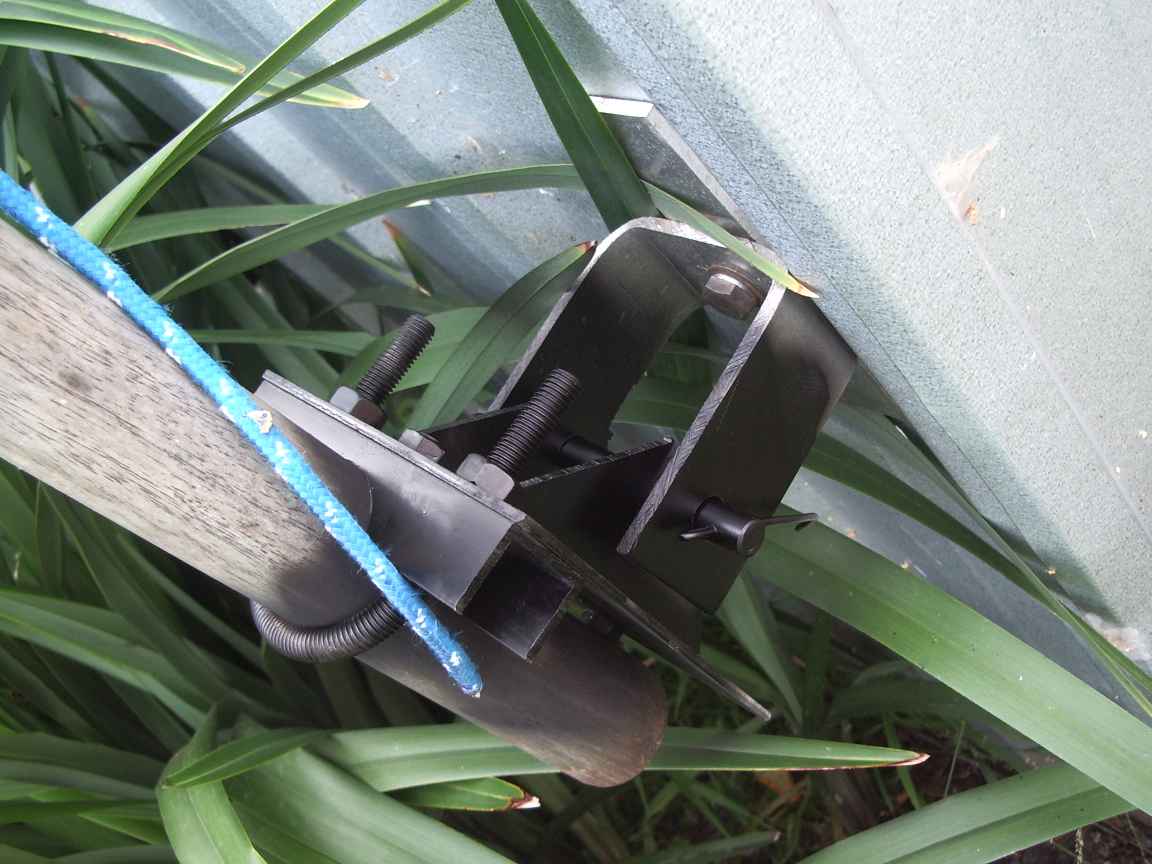
the saddle clamps were made by securing square U channel extrusion in a drill press and drilling the round cut out with a hole saw. Be very carefull if you try this at home.
the vertical thrust is taken by a vertical wood beam inside the shed
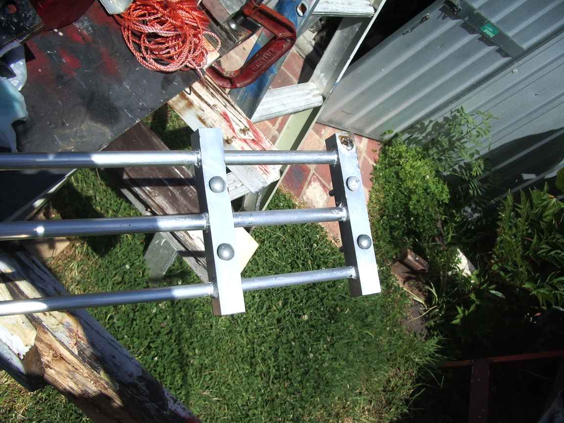
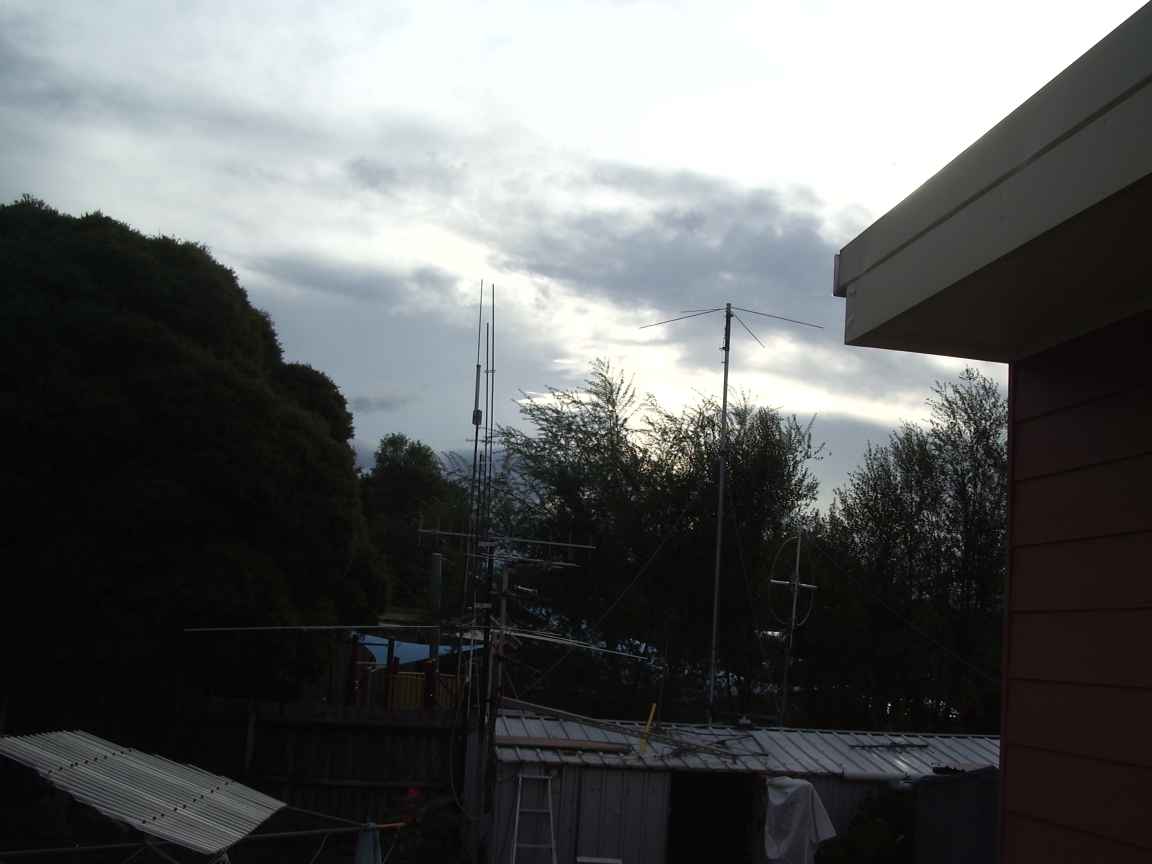
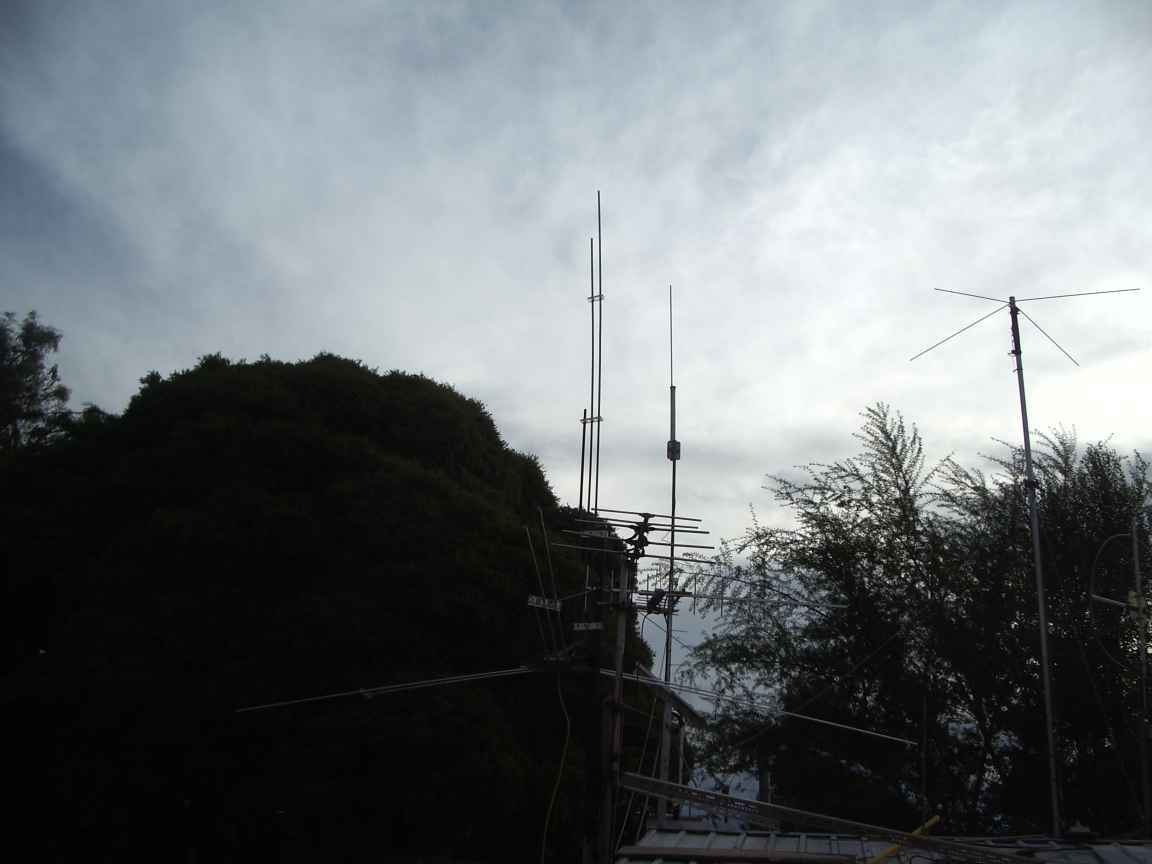
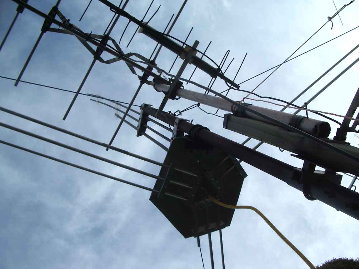
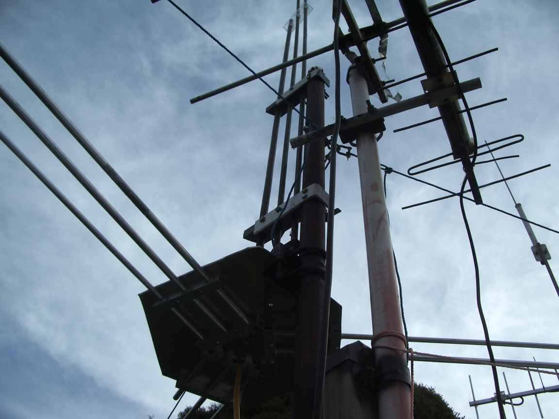
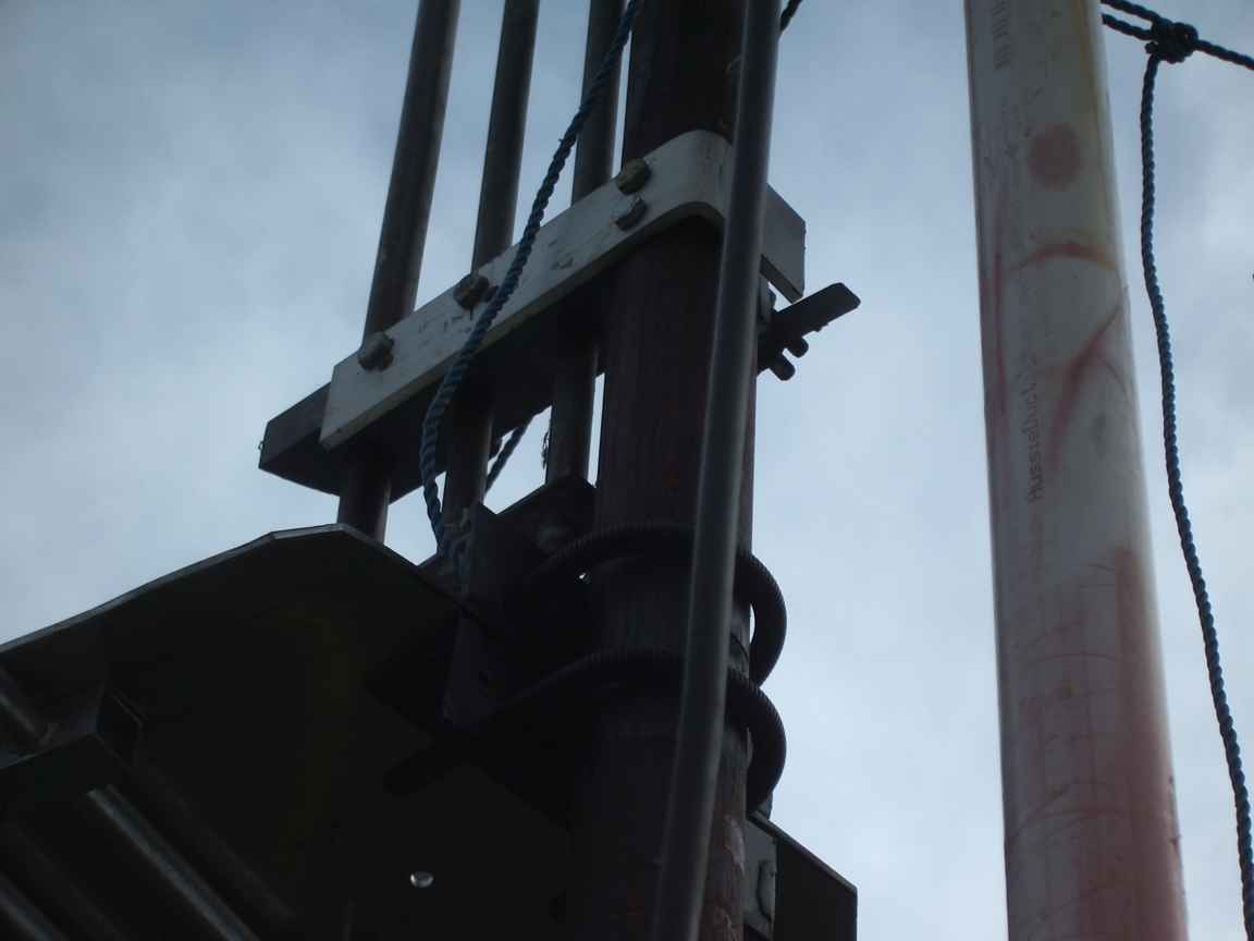
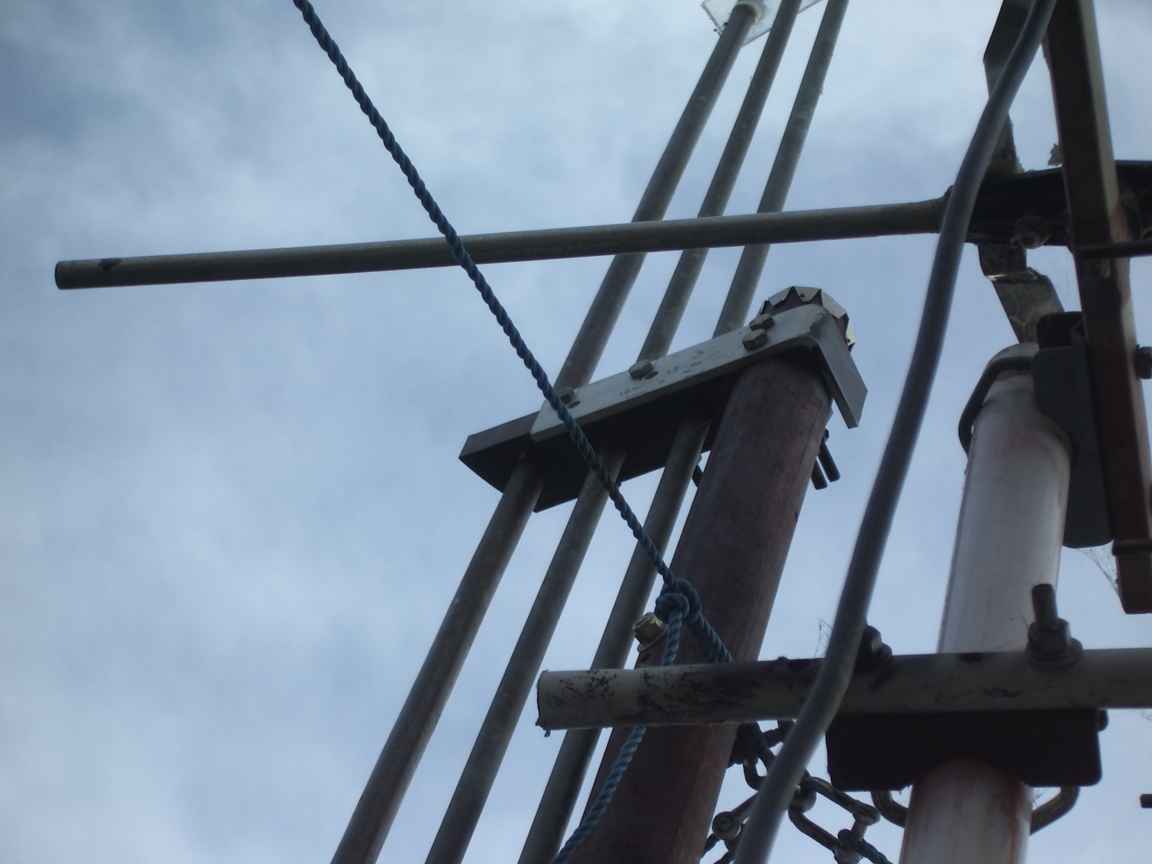
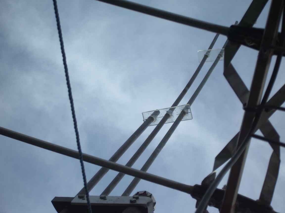
note that the wooden pole has a metal hat to mitigate rot.
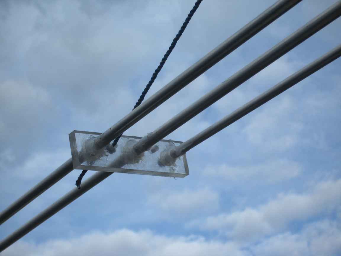
required to mitigate loading by birds
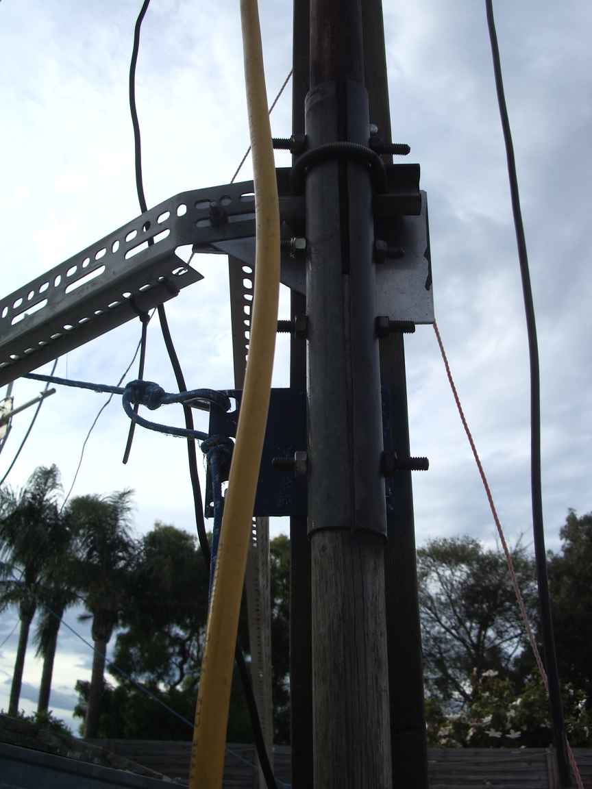
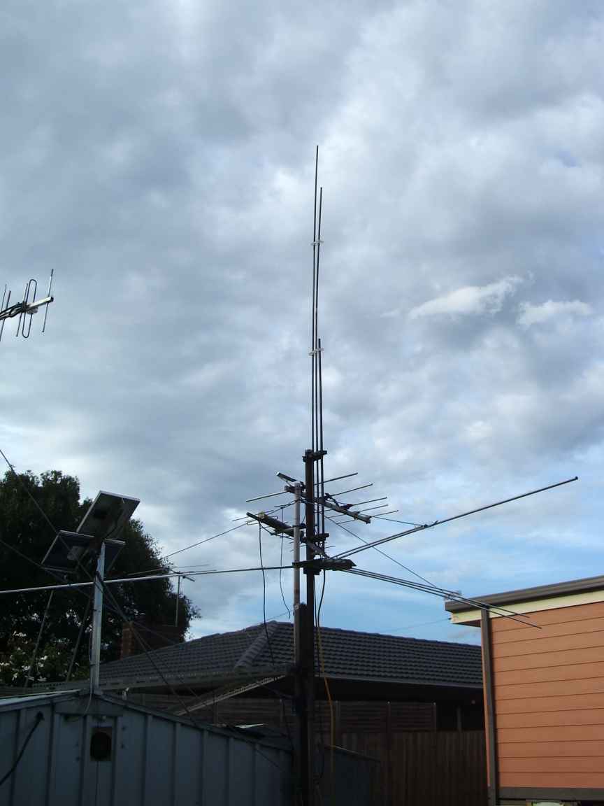
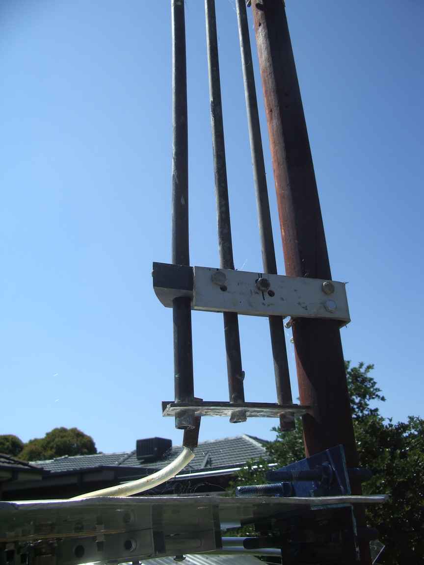
this is the splice , clamp and "compressive guying" to the shed structure
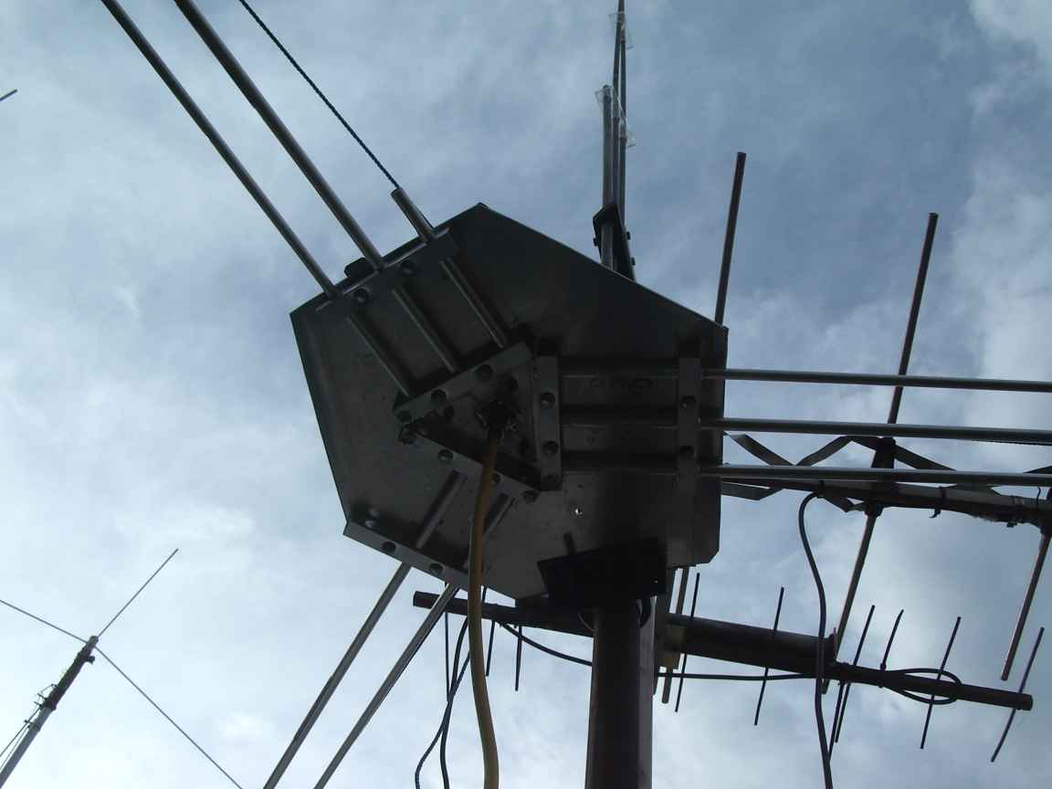
they are soldered to a heavy brass shorting bar
the grey material is solid plastic block of unknown origin
