TV and VCR tuner modules
How to use surplus modules.
abstract: analog tuner modules found in domestic VCRs and TVs can be used for whatever, if you know what the IO signals actually mean and what voltages need to be applied. |
author ralph klimek copyright: none, this article is copyleft, use it as you see fit.Circuits belong to their manufacturers date Jan 2008 |
I am sure that at some part in your
life as radio ham or electronics enthusiast you must have looked inside
the inards of a recently discarded VCR or idiot box and wondered to
what good use you could put the tuner module. The module has generally
wide UHF coverage and nearly complete coverage of the LOW
and HIGH VHF bands and completely eletronically tuneable.
Specifications are nearly impossible to come by. The really old
modules could be reverse engineered, but anything more recent than the
last 15 years has been extremely well made with micro miniature
components and reverse engineering them is out of the question. I
have noticed that the pinouts seen to follow some loose conventions and
the signal levels also appear to follow a loose convention.
I have come across some construction articles using these devices ,
usually for the construction of UHF spectrum analysers, making good use
of the fact that they are varactor tuned and can be scanned very
rapidly, but again the articles refer to very specific tuner models
that have only transient availability.
These two circuits came from a
service manual for a long gone vcr I once had and will provide enough
information as to application and voltage levels that will enable you
to use a tuner module for whatever. The only things that really
come to mind are spectrum analyser front ends or homemade tuneable
wideband scanners. The circuits show only how the module is
driven, nothing about the module internals is available. It seems that
there are only one or two companies that make these modules and they
are used by nearly all tv set and vcr makers. I think Phillips used to
make them as well. In fact they probably made them all! I have discovered that Phillips™ seem to have spun off their division that made these devices. They are now known as NXP and can be found here www.nxp.com. Good luck in finding a product spec for these older devices. This site lets you search by part number only, and these modules allmost never have a part number on them!
The tuning range of these devices seems to encompass about 400 to 850
Mhz, 130-230 Mhz and 45 to 110 Mhz in 3 seperate electronically
selectable bands. The tuning voltage requires up to 30V for
varactor reverse bias. I cant really tell what the AFT voltage
range is but I suspect holding it constant at some voltage between 0
and 12 is required. The power supply looks like it wants to be 12
V. The IF output has usually only one tuned resonator on the
output and I guess its centered on maybe 42 Mhz, but the Q is kept low
to keep the required IF bandwidth high. The IF output is low impedance
to permit small runs of coaxial cable to be driven.
My guess of the signal lines is as follows. Most tuner modules
have these pin markings appearing either on the module itself or on the
pcb to which its mounted. The nmenonics seem to be mostly consistent but mileage will vary.
More modern tuner modules are not tuned by externally supplied analog voltages. Modern ones contain digital frequency synthesizers and are tuned through a digital I2C interface. Good luck finding a product spec or programming guide, they do not appear to be public documents. |
| Analog tuner I/O pins. | |||
| UB | UHF band select | HI to select | approx 450 to 800Mhz |
| TU | tuning varactor control voltage | between 2 and 30 volts + | high volts is higher frequency |
| HB | VHF HI band | Hi to select | approx 135 to 240Mhz |
| AGC | AGC input | data sheets suggest low for max gain | mileage may vary |
| LB | VHF LO band select signal | HI to select | approx 45 to 108 Mhz |
| AFT | automatic frequency tuning input | something between 0 and 12 | probably just an alternative tuner input |
| MB | 12V DC power | main power | should be well regulated |
| IF | if output | lo impedance broadband | centred at about 42Mz |
It would appear that to select a band the appropriate select signal is
high (+12v) , the others should be permitted to float low. My
guess for the sense of AGC that it is a signal between 0 and 12V+ and
forward agc will be used for best linearity and low noise figure, so
that means as the AGC voltage goes up, gain should go down. It would
appear that on modern tuner modules PIN diodes are used to provide the
variable gain function. However some data sheets suggest the opposite is the case. I guess you just have to experiment.
The IF centred frequency is an educated guess, forty something Mhz has
been the traditional standard. The SAW filter that it feeds
should be the guide but its usually impossible to get a specification
on these.
What to do with one of these ? Dunno. I have collected a handfull in case I ever think of a practical use for one. Only one thing really comes to mind and that would be some sort of tuneable eavesdropper reciever, tuned with a 10 turn pot and a simple little up converter on the output mixed with 100Mhz with the tuneable IF being a 2 meter amatuer reciever. There are a number of easy to use single chip FM radio recievers that would make a suitable IF as well. (eg TDA7000). The span of these modules potentially covers the 6M 2M and 70cm bands .( and 200Mhz for USA hams) |
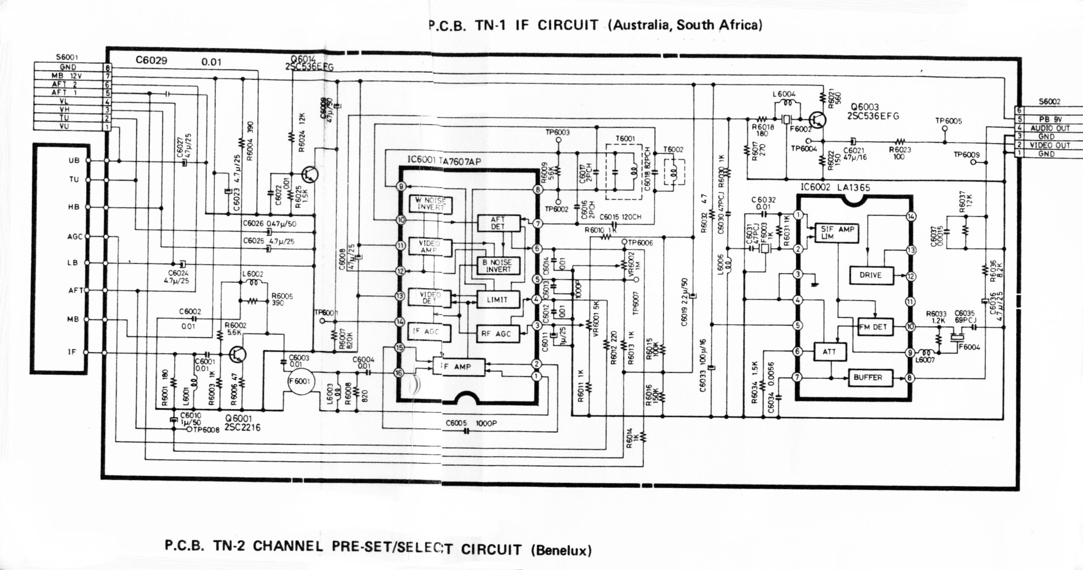
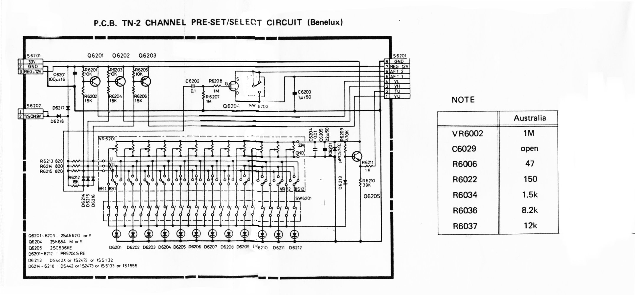
| IF interface and thumbwheel tuner for VHF/UHF tuner modules |
|
|
This should help to reverse engineer the tuner interface. This is the IF strip showing the tuner inputs. |
|
| this is the thumb wheel interface that selects a trimpot for low,high band vhf and uhf chanels. |
| Mystery UHF only tuner blueprint |
 |
| I found this blueprint of a UHF tv tuner on an obscure russian website. I have cleaned it up as far as the state of the art permits. The major differance between this and something more modern would be the current use of PIN diodes for AGC control rather than the second gate of a dual gate mosfet. Notice this design only has 300Ohm balanced input. It appears to be dated 1978, I cannot make out the manufacturer. I dont quite understand how the local oscillator is supposed to work here, but at least the interface requirements are clear. The use of a dual gate mosfet agc mechanism would make this design very susceptible to front end overloading. |