The
slotted line apparatus
for the precision measurement of complex impedance at VHF and UHF
frequencies.
A practical and precision instrument for the serious VHF UHF
experimenter
by Ralph Klimek 1982
copyleft: you are free
to copy and use this article and images as you see fit
This instrument was biult by me to permit the measurement of actual
complex impedance for antenna arrays that I was atempting to
biuld for the 2 Meter amd 70 CM amateur band. It can be used with a few
other accesories to measure the true SWR on any line. It is the true
measure of whether or not your VHF antenna is or is not a good match.
The length of this instrument even permits measurements down
to
the 6M meter band, however to be meaningfull at this low frequency you
must make some precision stub cables. The other required accessory is a
high impedance 10Mohm voltmeter.
The unit is made from off the shelf aluminum extrusions. The formulas
from assorted engineering handbooks gives a characteristic impedance of
about 52 ohms for the stock materials and ignoring the effect of the
slot for which there is no formula. As the slot opening is
less
then 10 % of the perimeter of the overall line, the effect of the slot
should be negligible. I have yet to evaluate this with an
excellent arbitary line calculator tool called
atlc.
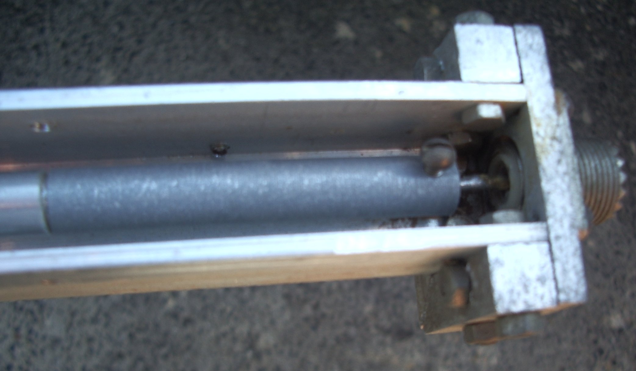
The only real construction difficulties arise where the inner conductor
is joined to the coax connectors. In the ideal scenario there would be
a tapered transistion to minimise the inevitable reflection arising
from the change in dimension of the conductors. I had to use
hollow tube for the inner conductor. This, and the fact that
it
was aluminum made it hard to terminate to real world type N or PL259
connectors. The image shows PL259 connectors which are horrible at UHF
and only just barely acceptable at VHF. I have since replaced them with
type N and have no regrets. When I made this in 1982 Type N
connectors were very expensive (for the hobbyist).
The connection to the coaxial connectors was originally made with
horrible grounding lugs. Later when I had access to a lathe I machined
a nice transistion piece which has proved very satisfactory. If I was
biulding this instrument again from scratch I would use hard drawn
copper tube to permit direct attachment to the coaxial connectors, or
alternatively, solid aluminum rod with a drilled out hole at
the
end with a threaded boss to permit a solid connection to the coaxial
connector.
If you do not have access to a lathe for this step, you can use a
poor mans lathe. Secure a small length of solid cylinderical rod in a
drill press and file the excess away ! Cheap, horrible and nasty but it
does work. Warning its also highly dangerous !
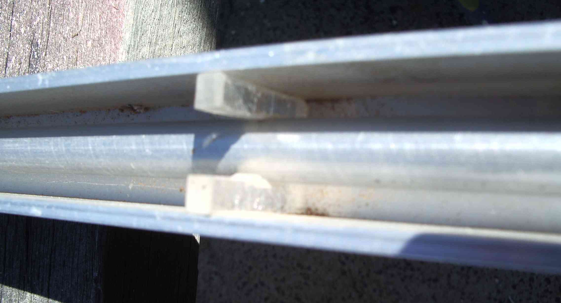
There is only one element of precision required in the assembly. This
is the spacing of the inner conductor. Its absolute spacing, as it
turns out, has very little bearing on the characteristic impedance.
However, the distance between the probe and the line must be kept as
uniform as possible because the probe pickup voltage is quite
sensitive to the spacing between it and the centre conductor.
Make sure that your inner tube is not bent, if it is, reject
it
and buy one that isnt bent! I have made two perspex spacers which
mitigate sagging. File some slots in the four mounting screws
of
the Type N connectors to allow for about 1mm of vertical adjustment.
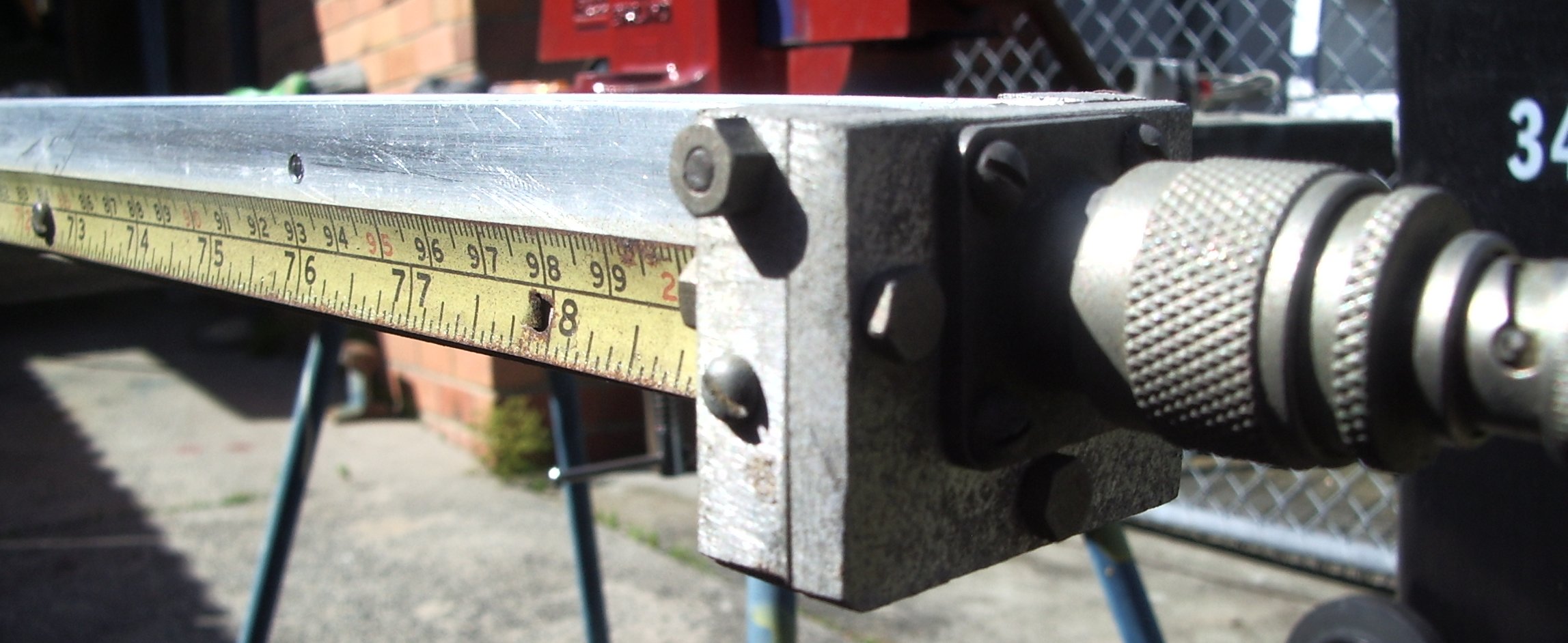
Use the depth gauge of vernier calipers to ensure that the conductor is
trully parallel with the slot. You can see from the pictures that I
have allowd the end plates to be slightly adjustable so as to permit
precision alignment.
Practical uses.
Even if you cannot
understand the very difficult to master Smith Chart
or the complex equations or transmission line theory ( as I havent yet!
) this apparatus still permits quick and dirty antenna
matching
alignments because you get a very readily accessible indication of SWR
by directly observing the standing waves ! A "flat" line or
well
matched load will present little or no variation as you move the probe. It becomes obvious if the load impedance is
above or below Z0 from the position of nodes and the relative amplitude
of the nodes quickly gives you a qualitative idea of the size of the
resistive component. It is the ultimate tool by which SWR
meters
can be calibrated. I have found that half a watt is sufficient power to energise the line
and load to get meaningfull readings from the probe. The line
should be fed from a 6dB pad to minimise spurious reflections from the
transmitter end.
The probe diode must be a germanium point contact for best results.
They have the lowest forward voltage drop , minimum junction
capacitance and will maintain maximum acccuracy and superior
sensitivity. The old faithfull OA91 diode is still readily available
and still rectifies at microwave frequencies.
Things I would have done differantly after 25 years.
Copper tube inner, used
silver plated Type N connectors, perhaps 3
meters was too long to be really practical. Approximate methods work
well enough at 6 Meters ( 50Mhz ) . The probe presents some difficulty.
The DC output voltage of the simple diode rectifier is not a
simple linear function of the the line voltage. It has frequency
dependency because we are sampling the line voltage field with a
capacitive probe, and the indicated DC probe voltage is a non linear
function of the line voltage and voltmeter loading. True measurements
require you to calibrate the transfer function of the diode probe ,
construct a table, and from the measurement infer the line voltage. As
a first order approximation the probe can be calibrated from a variable
DC voltage source, and this should be sufficient precision
for
amateur use. Perhaps the next probe will have a broadband
MMIC
amplifier and an INDUCTIVE probe. Select metal stock on the basis of first having simulated the lines with
ATLC the arbitary transmission line calculator so as to get the nearest fit to 50Ohms
Z0
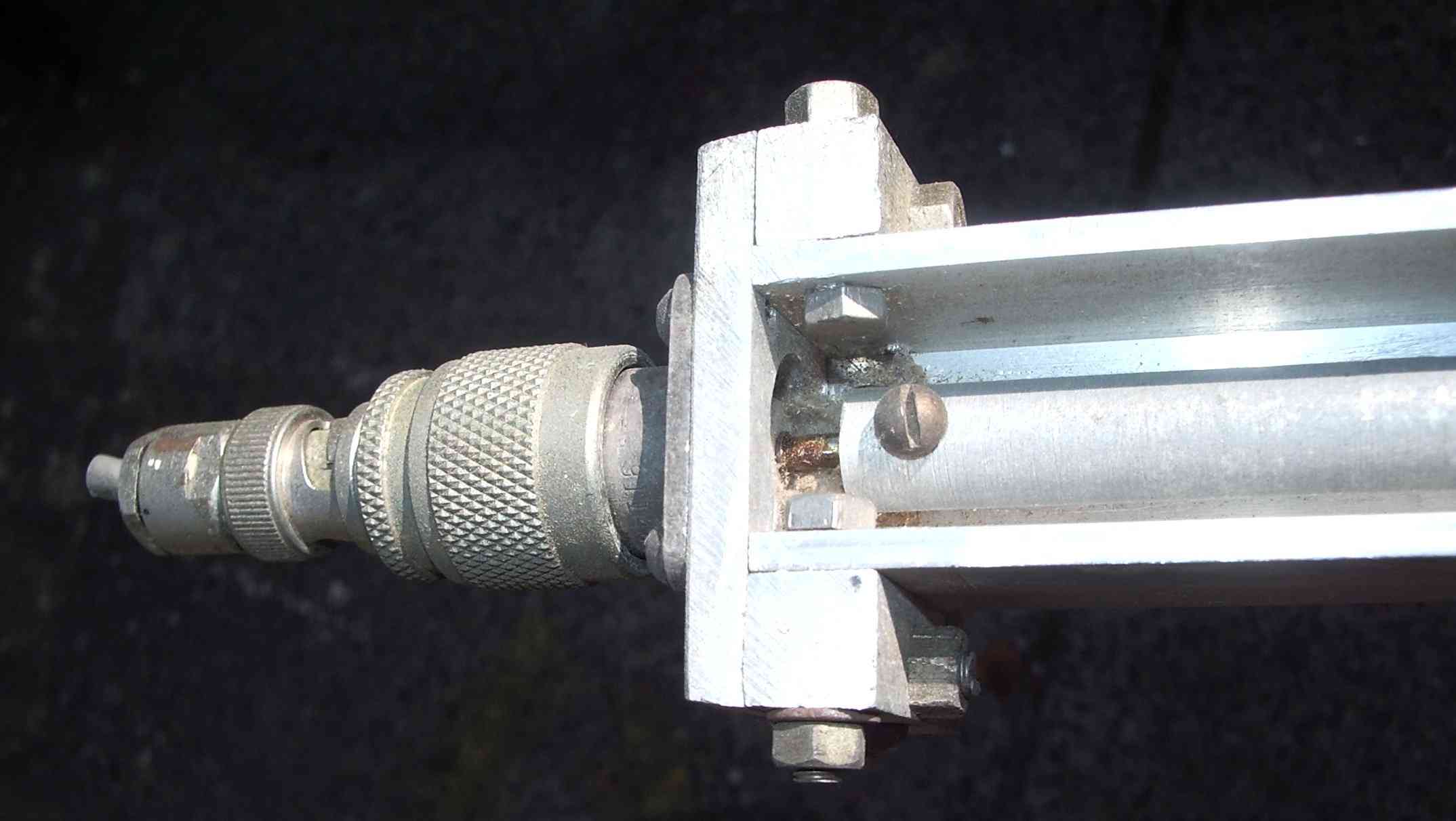 |  |  |
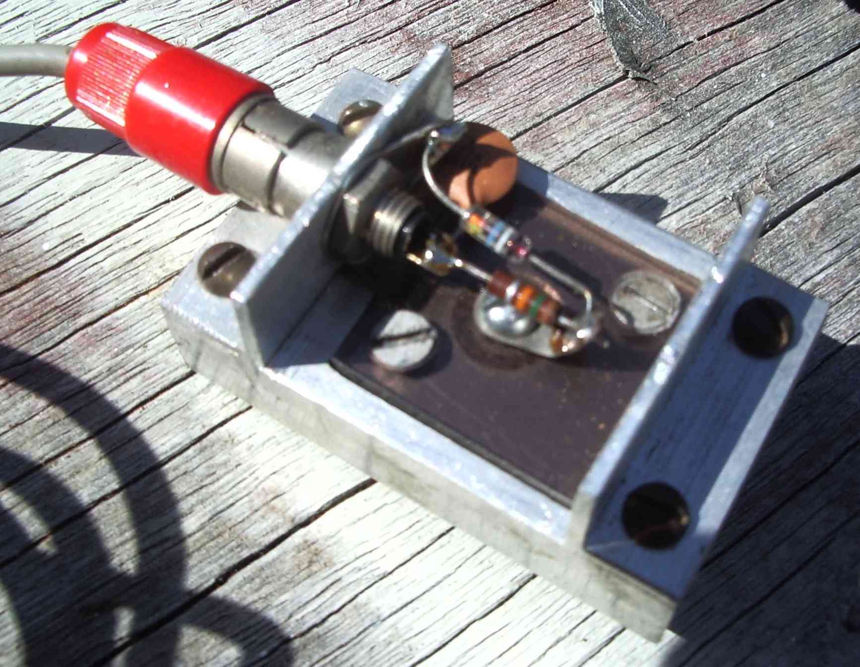
Here are the line to connector transistions.
These were machined on a
lathe but use solid rod
and a handheld drill is all thats required to
make the connector transistion.
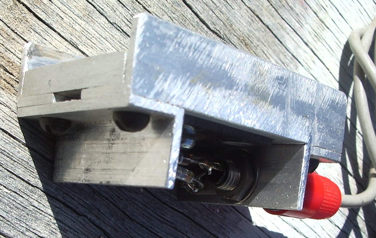
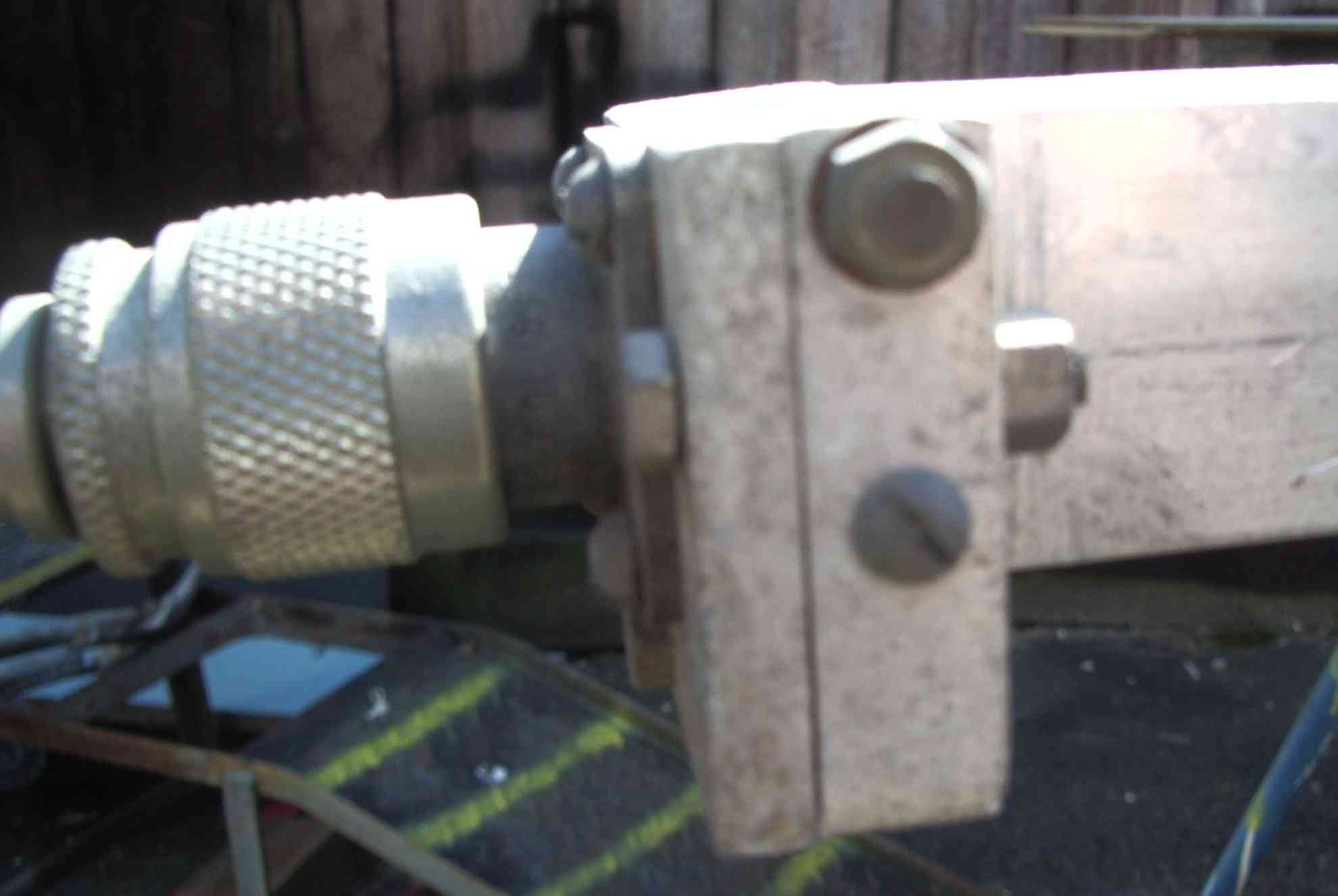
| the horrible pl259 sockets have since been
replaced with type N, the only acceptable socket
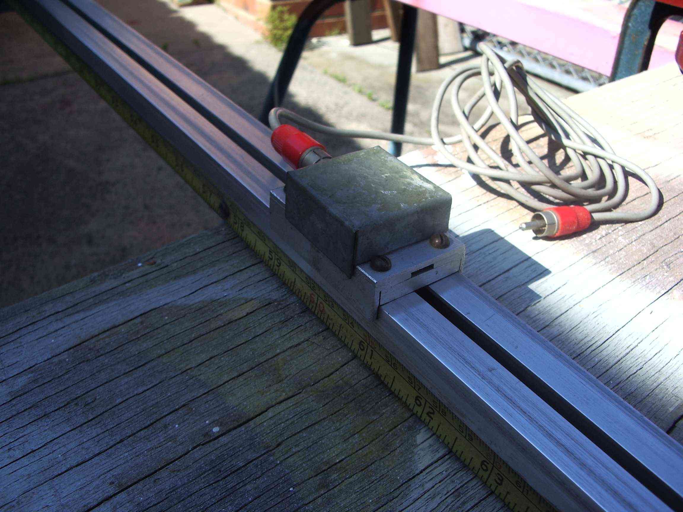
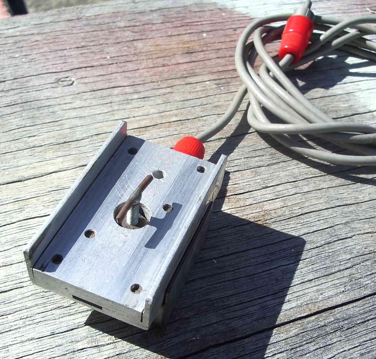
instruments like this | methode of securing connectors to main body of slotted line |
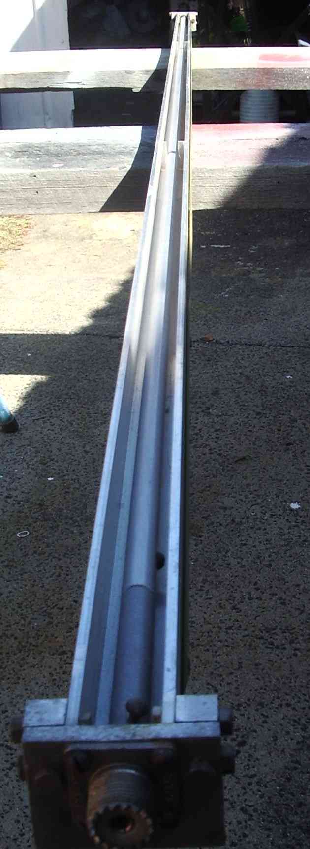 | a lengthwise view with the top slide cover removed to reveal the central conductor |
The scale comes from a replacement tape measure blade. These days just
buy a cheap and nasty tape measure and use the blade from it. A pure
metric blade is best. Two angle stock pieces form the top cover and the "slot" in the slotted line body.
The
internal conductor line requires some support to prevent sag. The
minimum amount of support is required otherwise the electric filed
pattern can be distorted.remember to slot the supports to allow
the probe to pass.
 |  | 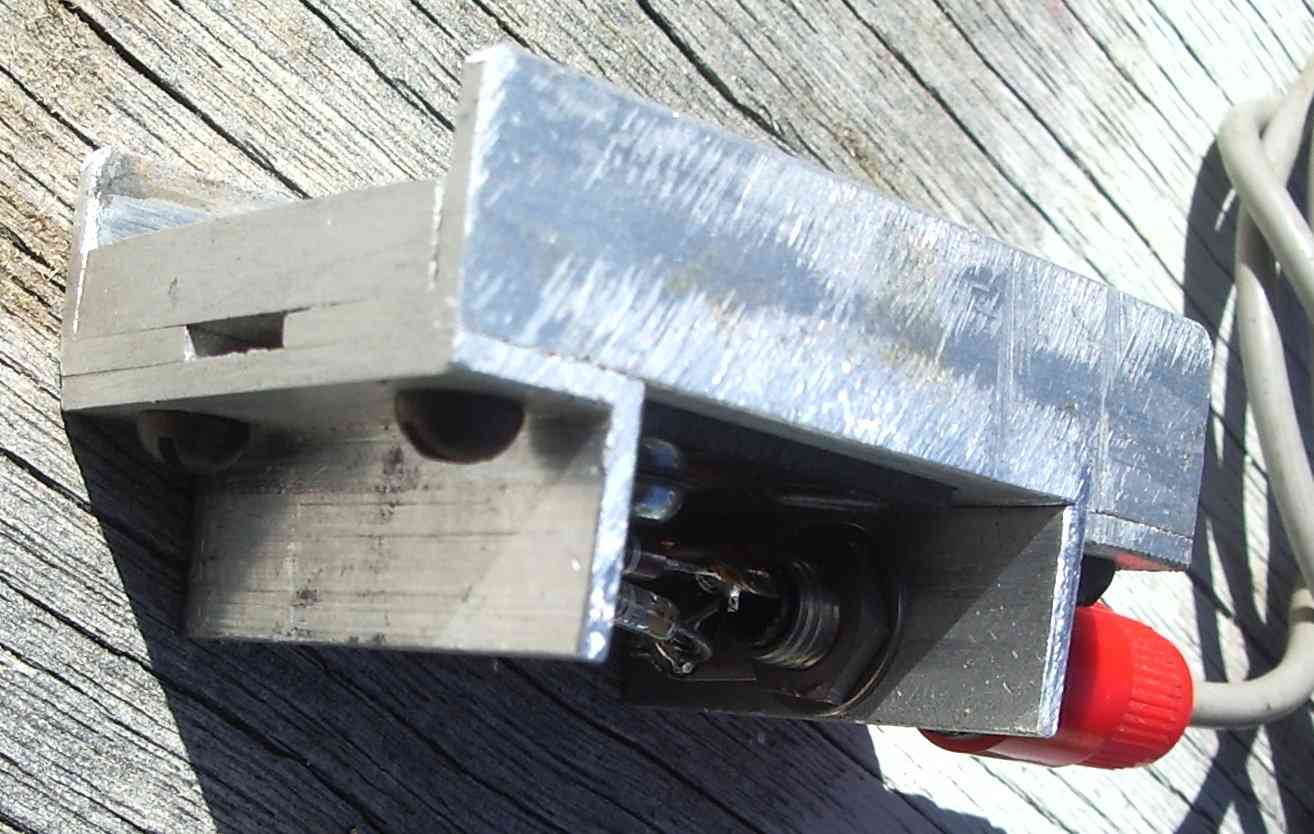 |
| capacitive probe | simple Ge diode detector | made from small angle stock |