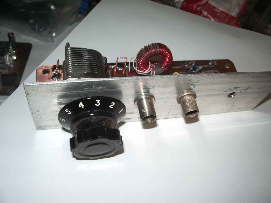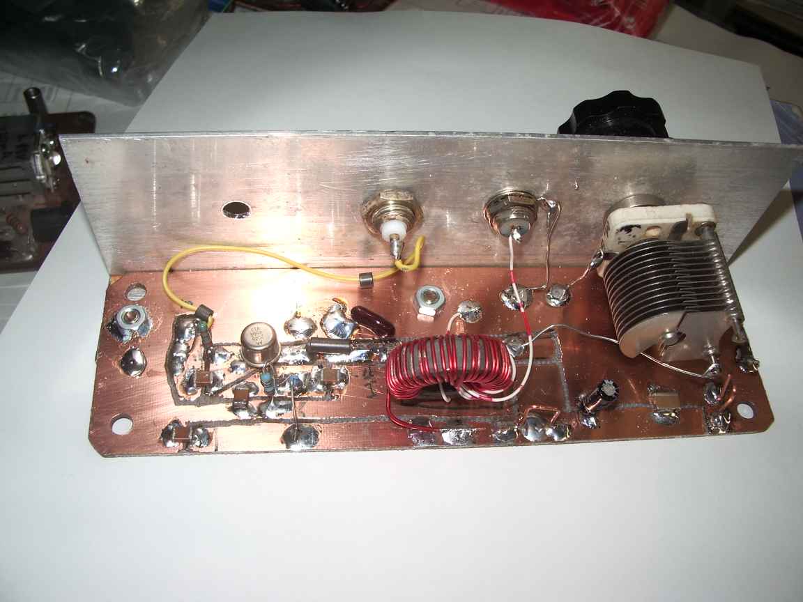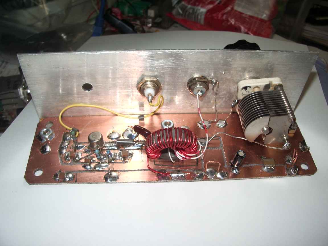
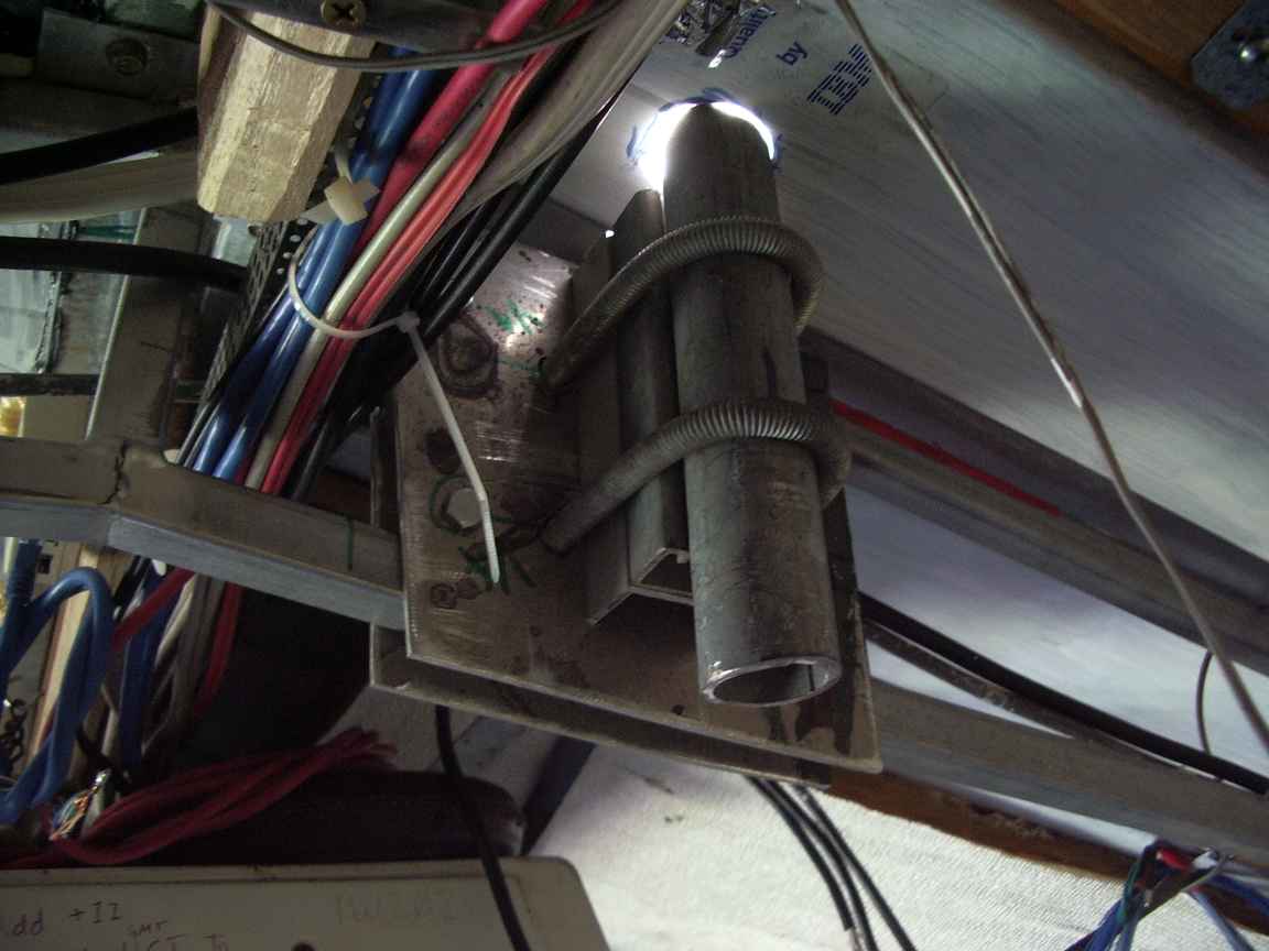
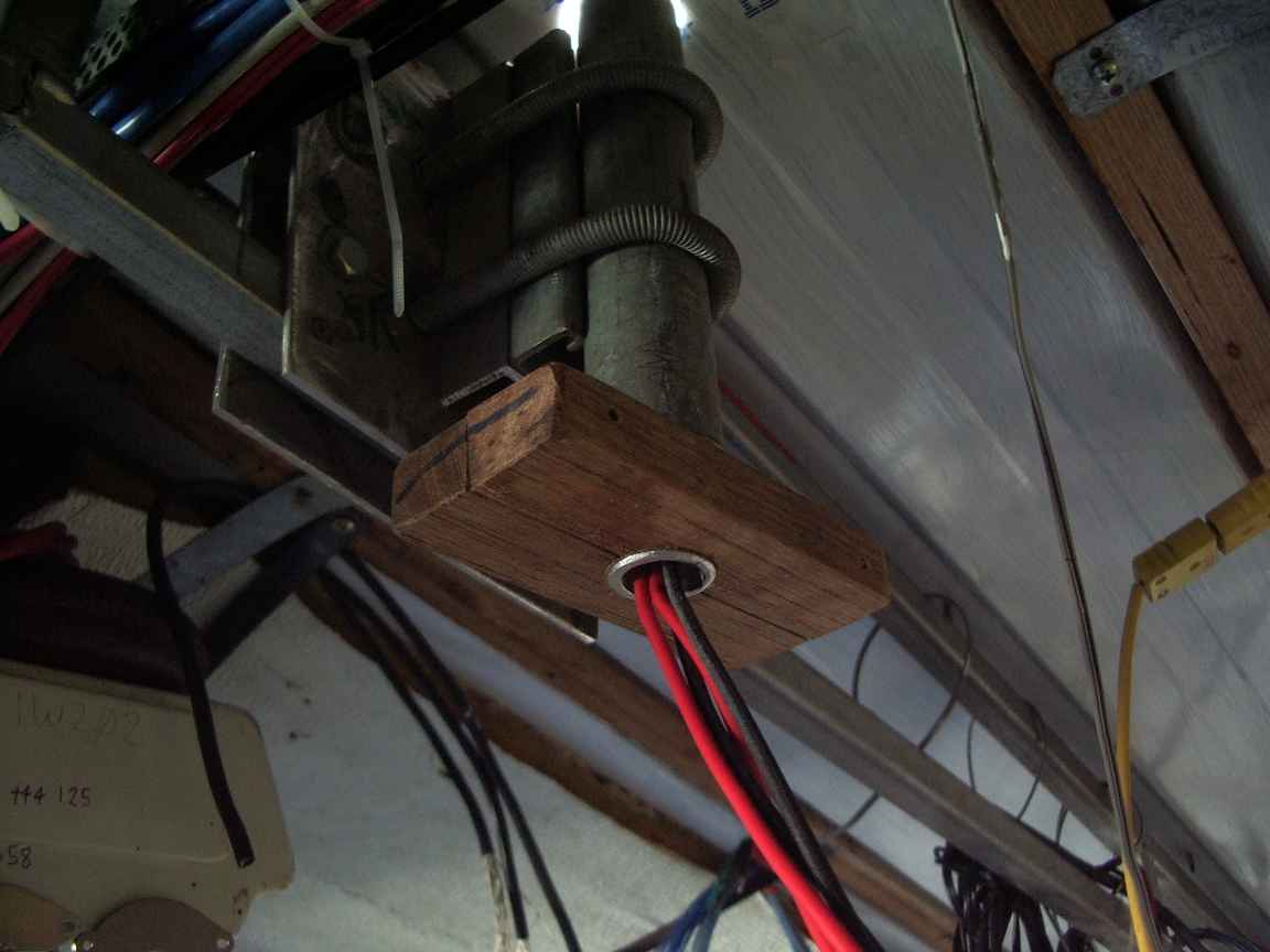
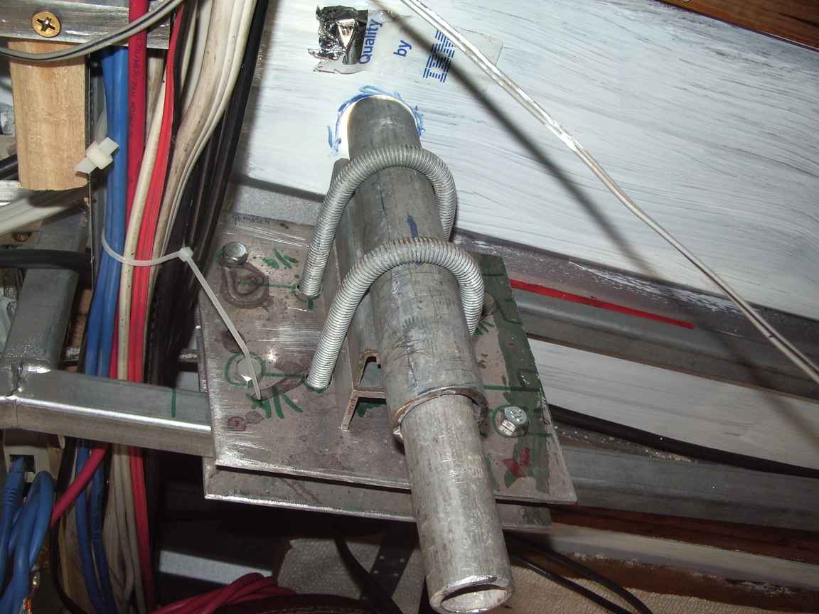
construction details.
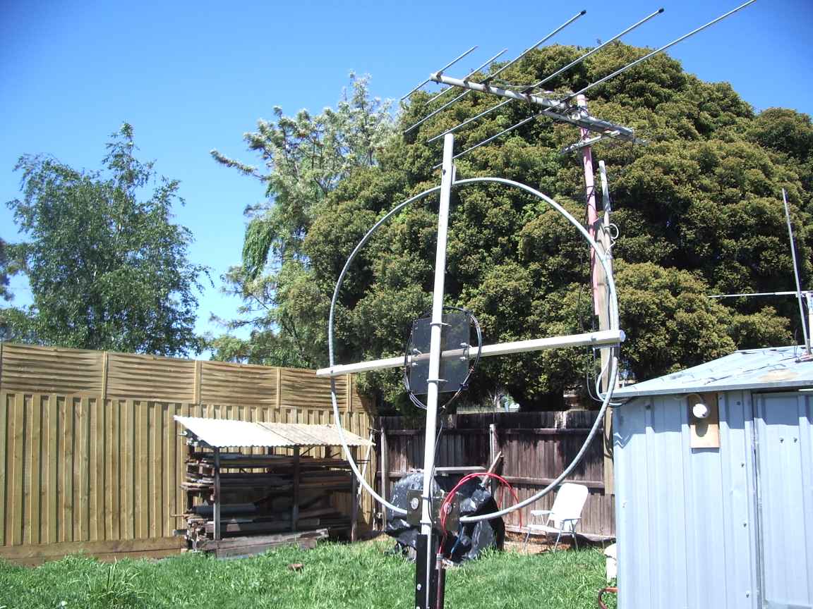
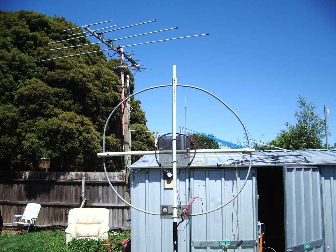
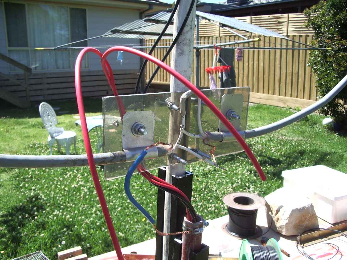
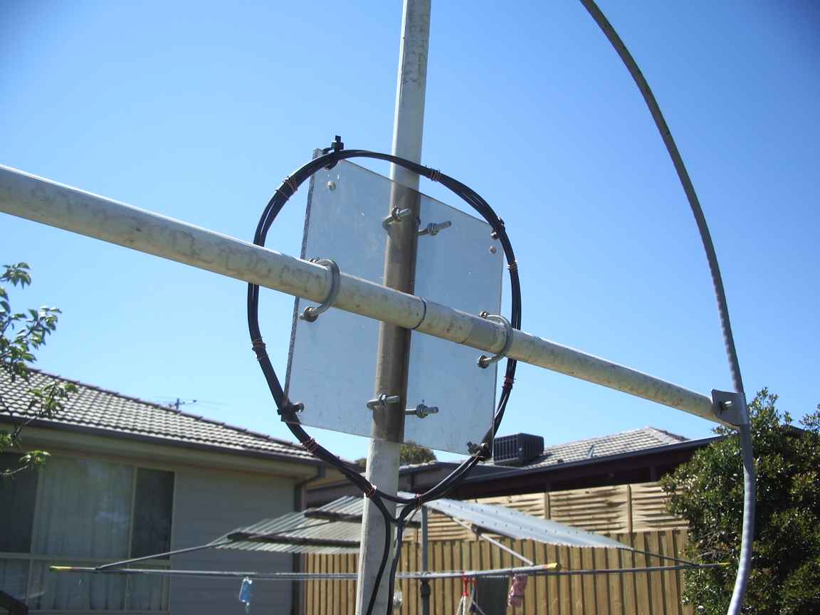
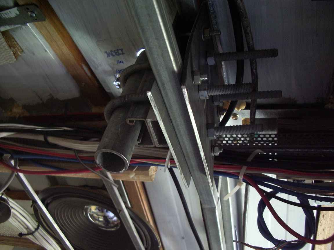
The loop is wound with Hubner and Suhner "Radox" (tm) industrial instrumention cable. This expensive solid copper armoured and shielded cable is used in industry for control box cabling that need armouring and shielding. I found half used discarded drum of this expensive and excellent cable in a dumpster at work. The solid copper sheath surrounds two conductors insulated with mica and a high temperature insulator with a heavy gauge pretinned conductors. Sorry, you cant have any ! Its very stiff and the solid copper sheild makes it allmlost self supporting. This stuff will form the basis of the transmit loop, in the fullness of time. Distributed capacitance is between that of RG8 and RG6. The conductors have been joined to make a two turn coil. The loop conductors and pickup coil are brough down in the inner rotating tube to a variable capacitor mounted just under the roof.
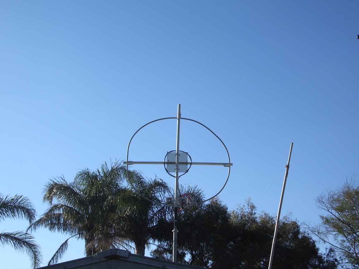
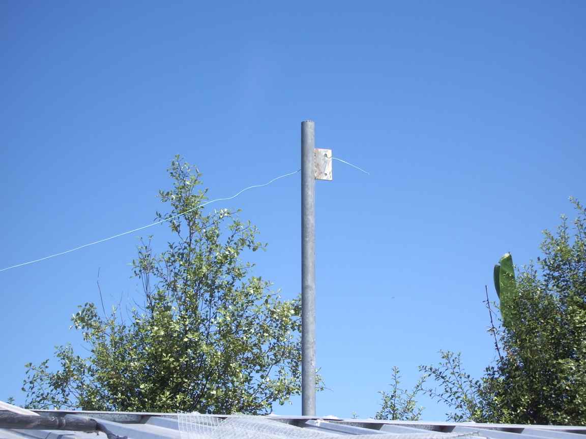
The fully rotatable mount consists of two concentric tubes, the inner can rotate and the conductors are threaded through this. There is a homemade thrust bearing at the top. The central pole also mechanically supports the loop. The loop arms are made from 25MM PVC electrical conduit which has just bearly enough mechanical strength for this job. The central spider is perspex.
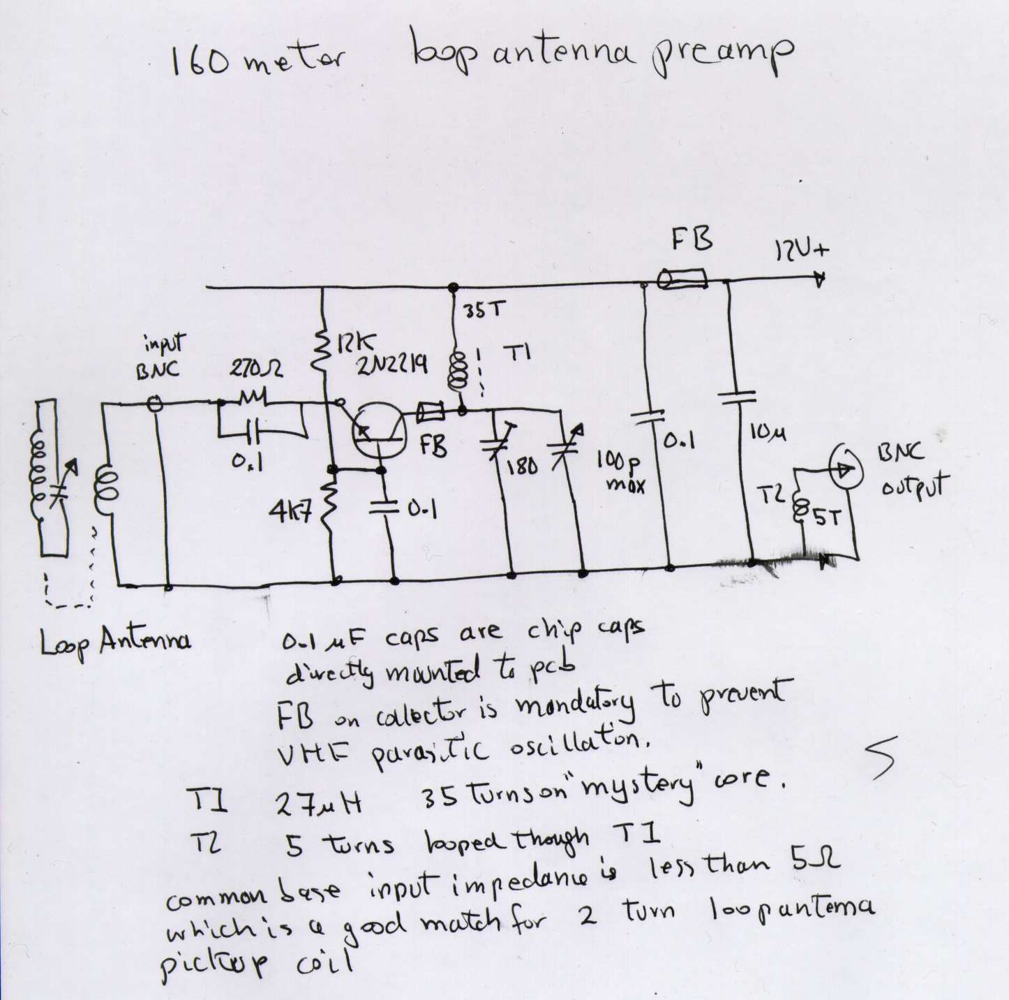
I have found that a low noise pre amplifier for 160m reception through this loop is absolutely essential. The very low efficiency of the loop antenna is only compensated by its ability to reject noise , which in the suburban envoironment is extreme. The loop will resolve signals that are totally inaudible with the main 160m vertical antenna.
The common base configuration gives this amplifier an extremely low input impedance, of the order of 5 ohms, so it makes a particularly good match for the low inductance pickup coil in the center of the sheilded loop. At this low frequency just about any modern solicon transistor will do, I chose a 2n2219A because these have usefull gain up to 150Mhz and their 1 Watt rating means that a sensibly large amount of collector current may flow, which gives good immunity to broadcast band cross modulation. The ferrite bead in the collector is required to prevent VHF oscillation. The presence of parasitic oscillation is indicated if there is a huge amound of broadband noise and no evidence of real signals.
I have used 0.1uF chip capacitors, their low parasitic inductance makes them ideal bypass and RF coupling capacitors. The collector inductor was made from a mystery found toroid that exhibited a usefull Q at 2Mhz and sufficient turns wound to make up 27uH. I used this method , first , to ensure that the coil would work as required. The Q is sufficiently high to require the use of a variable capacitor on the output to peak tune the whole 160m band. There is sufficient capacitance reserve to permit tunign down to the top of the broadcast band to permit hunting for broadcast band DX on the loop.
