An advanced analog filter radio
teletype recieve decoder modem design and diagrams
author and designer Ralph
Klimek 1987.
document date may 18 2007
An analog computer is
the basis of the RMK mark2 rtty decoder.
This RTTY hardware modem/decoder was designed and biult by me in 1987,
and still exists but hasnt been used in years due to the gradual
disappereance of any meaningful quantity of RTTY transmission on short
wave.
I designed and biult this device to monitor and decode RTTY
transmission from the shortwave, mainly being interested in the various
news wire services many of which had a shortwave service for their
customers that for geograhical and often political reason could not
have a wired land line news feed. There used to be many interesting
news and propaganda feeds from behind the Iron Curtain and Rueters,
Associated Press, AAP and other more crazy ones like KCNA with their
continuous 24 hour reverential coverage of their wretched Great Leader.
The nature of shortwave radio transmission puts unique impediments
tothe recepetion and decoding of these radio signals. The RTTY signal
is pulse frequency modulated with various frequency shifts and coded
with the 5 level Murry or Baudot code with no scope or ability to
correct or forward correct errors in transmission. RTTY
signals
should have about 300-400Hz of signal bandwidth. The signal is very
prone to outright fading and differential fading, that is the
ionosphere path loss is sharply frequency dependant
My design philosophies were:
- Track the fading and compensate,
- Track differential fading and compensate,
- Perform "intelligent" predictive bit slicing,
- Use the minimum bandwidth in the decoder so as to take
advantage of the
channel signal to noise gain inherent in narrow bandwidth design,
- Matched filters, to best preserve the pulse response.
- Dont through away any analog information until the bitter
end (just
like the government... dont make a firm decision untill you absolutely
MUST!),
- Minimise RF noise originating in the computer from finding
its way back into the communications reciever up the audio path.
All this is now done in commercial DSP decoders now, but in 1987 this
was beyond my grasp, so it was all done with op amps and a few trimpots
(to cope with my lack of design expertise...why else use trimpots!!!)
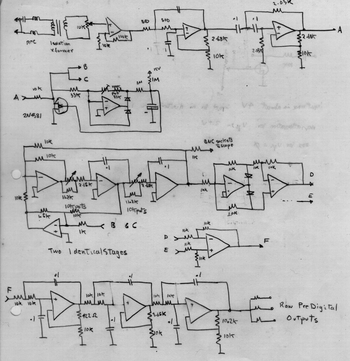
Circuit description, refer to the block diagram.
Audio input from a communications radio goes through a coarse manual
gain control, transformer isolation for RF noise mitigation, 2.5khz
audio low pass 1khz audio hipass filter and a simple AGC stage. The
audio bandpass filter mitigates against strong adjacent channel
interference and high frequency audio squeels and means that the
communications reciever need not have an IF response optimised for
RTTY. It also rejects hum. The AGC is not meant to track
rapid
fading, this is done
automatically later, but merely to set the mean operating set point of
the decoder. This makes it sensibly insensitive the the communications
radios volume control.
The RTTY signal now comes in as two tones, bandlimited noise between
1-2.5 khz. This band was chosen to make search for RTTY signal by ear
easy and made the creation of Hi Q audio filters that dont ring easier
to achieve. It is easy to make a filter of HI Q at say 800Hz but you
allmost certainly cannot stop it ringing. The other reason is that the
two audio filters must be independantly tuneable and have sensibly
constant gain as a function of their tuned centre freqencies. This is
HARD to do. It is easier for say 850Hz shift RTTY if this is done at
about 2khz, whereupon the design of tuneable audio filters is easy.
The output of the tuneable filters now consists of a short pulse of
noisy 1kzh and (say) 1.8Khz which represents binary ones and zeroes, we
dont quite know which, at this point we neither know , nor care.
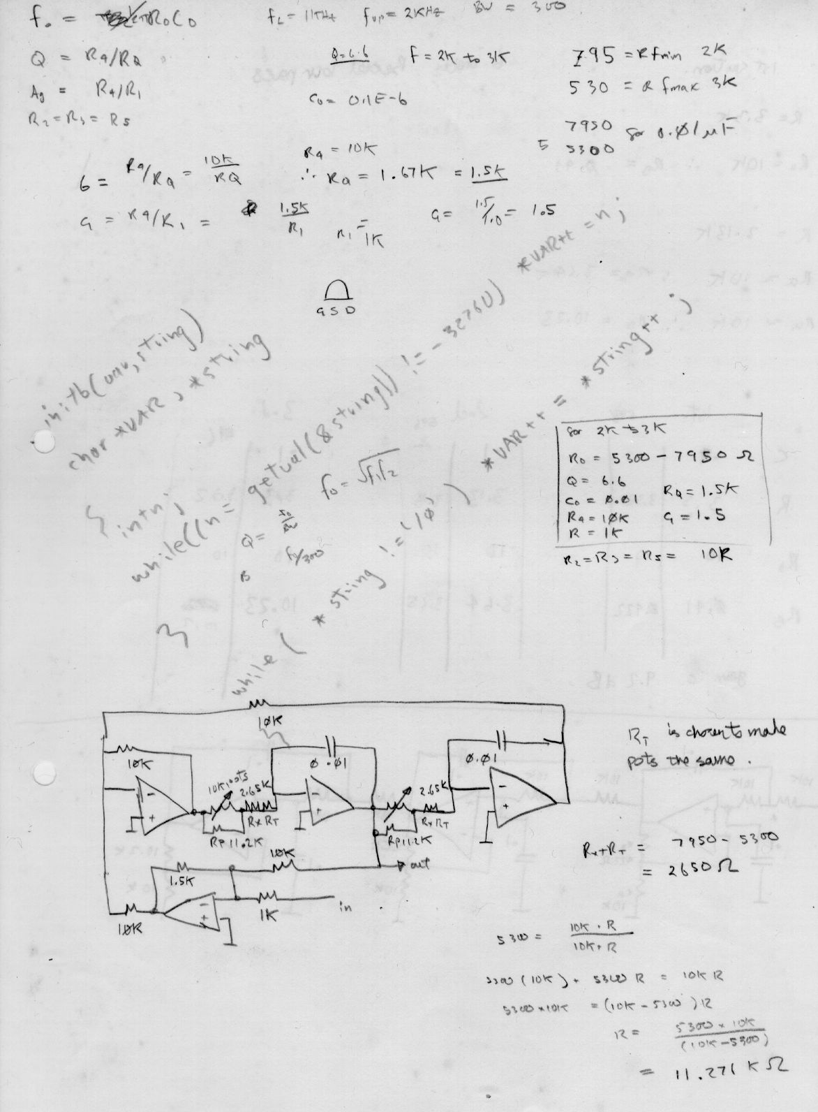
The tuneable filter also deserves some discussion. Classical RTTY
decoder/modems use a variable Hi Q tuneable peak filter. The peak gain
of these is a strong function of centre frequency. I have chosen to use
a tuneable bandpass filter whose peak gain is a constant. The
design here is directly taken from an article in Electronic Design News
from sometime in the 80s, I have lost the orginal journal. This filter
design with controlled Q also eliminates the ringing problem.
The
filter is based on the so called state variable filter and I choose
this because even though it is more complex than a simple op amp
filter, its parameters may be easily and independantly controlled and
as a bonus the design effort is trivial. The bandpass frequency can be simply controlled with a dual gang pot.
The outputs of these filter now goes to a proper opamp mediated full
wave rectifier, or rather , an absolute value generator. We
now
have two analog audio asymetrical pulse trains representing ones and
zeros. We have not thrown away ANY analog data yet. The
bandwidth
of the tuneable filters is still quite large, actually too large to do
any real filtering, we are merely using these tuneable filters as a
frequency discriminator. The ouputs of both absolute value
generators are now analog subtracted. The output of the subtractor , on
a scope, is now acutally beginning to look like digital data, its still
mostly noise and individual audio pulses, maybe a binary bit has about
10 to 15 audio pulses . We dont really care how many , we
will
make the ONE or ZERO decision LATER ! and that design will be
"rationally" based on averages.
The outputs of the absolute value generators is then subtracted from
each other.
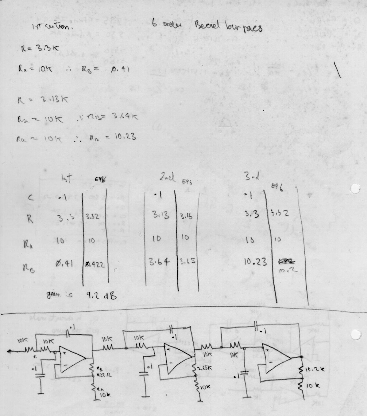
The output of the subtractor now goes to a carefully chosen low pass
filter that has response down to DC. The filter is a 6th order BESSEL
LP filter with a design bandwidth of 300Hz. The BESSEL filter was
chosen because it best maintains the shape of the digital pulses. It is
a joy to track the signal with a scope through this filter. It starts
as random looking noise pulses and stage by stage it transforms to a
nice clean very digital looking waveform at the end!
At this point most classical RTTY decoders would have had a simple
comparator (slicer) and then presented us with a digital serial pulse
train for our teletype or computer. Being more than usually pernickity
I added hysterisis. My mark 1 decoder did this, it certainly
worked but was completely unable to recover a signal from radio paths
suffering from rapid fading and differential fading. Hysterisis is a
great way of cleaning up a messy analog signal but classical hysterisis
comparators require a signal that is symetrical and twice the magnitude
of the hysterisis feedback signal, this is thus not very helpfull when
dealing with typical RTTY signals.
The solution I choose was to make the hysterisis feedback signal a
function of the amplitude of the RTTY analog signal. That solves the
rapid fading problem without the hassle of AGC. Good low audio
distortion AGC done with variable gain elements are hard to
design. The differential fading problem was
addressed
by modulating the hysterisis feedback offset level and making this a
function of the differance of the average value of the tuneable filters
output. That way the hysterisis set point could track dynamically the
differential fading. The effect of differential fading is to
shift the average DC value of the Bessel filters output.
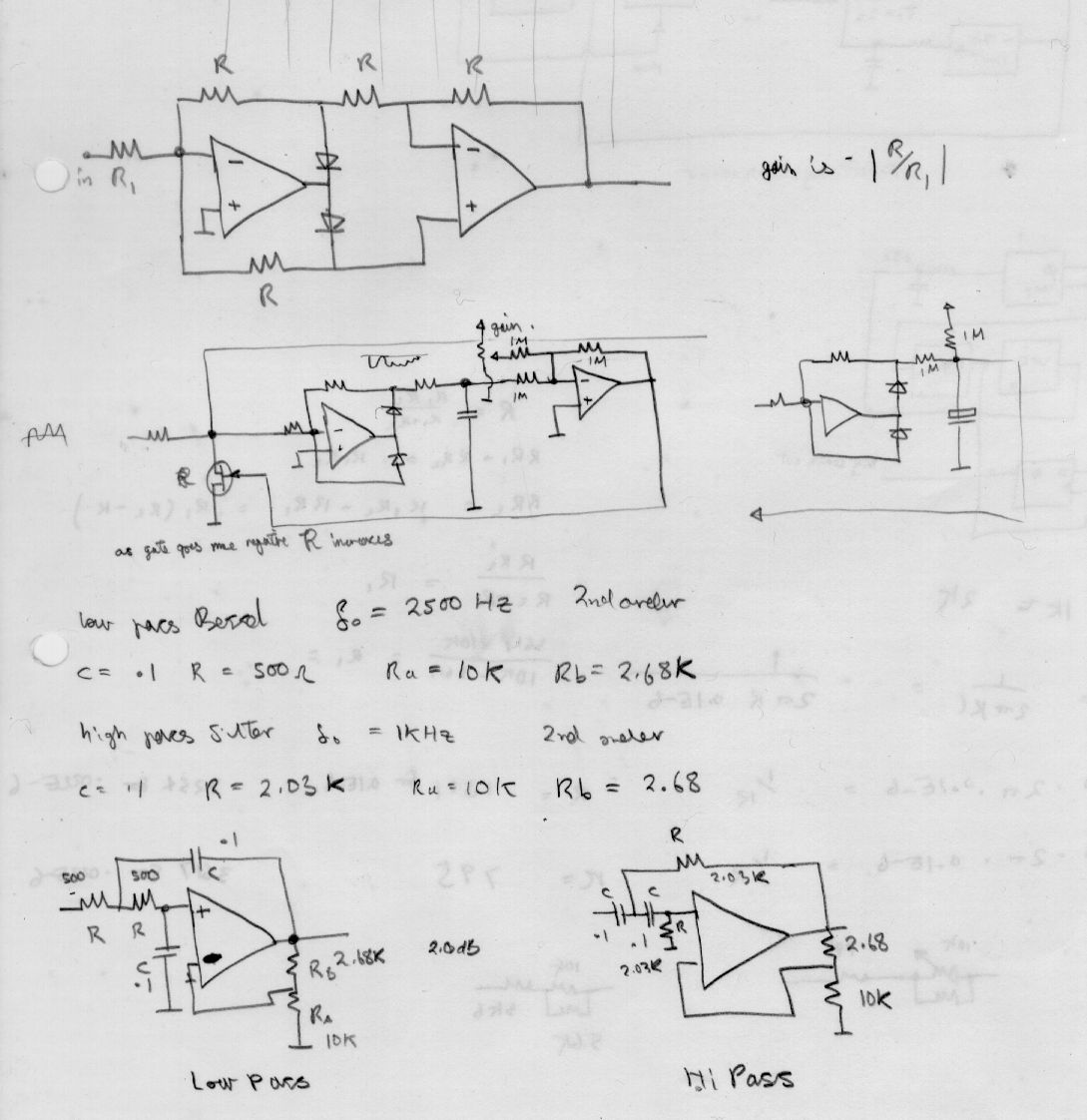
A rather remarkable op amp circuit called the bi-phase amplifier is
used to generate the hysterisis feedback signal. A bi-phase amplifer
has the remarkable property of having a gain of one or negative one
depending on the state of a simple control signal, in my case the final
digital output signal. All thats needed now is to select or
control the digital polarity to put it into a fit state for a UART.
The performance of this RRTY modem was rock solid, reliably recovering
error free RTTY from signals that were ,by ear, totally obscured by
noise, and on audio monitoring ,would recover usefull data from signals
in which on listening no discernable RTTY was apparent, such was the
beauty of the Bessel filter. (Mind you, this filter will turn genuine
white noise into unbelieveable data!)
My drawings are presented as is, mine worked, dont try to duplicate it
exactly but use it as a source of ideas. You can use the
Bessel
filter vebatim, in fact you have to! It took a long time to get the
component values right. Use a capacitance meter to get the caps right,
commercial caps have way too much tolerance. I used 0.1uF cheap TTL
bypass caps but they have a 50% tolerance, you must measure and select.
You may have faith in and believe the circuit values for the tuneable
filters and the Bessel filter.
Whats left on RTTY ? All the commercial services and most utility
signals have gone to satellite or leased line. There are still a few
Radio Hams and some coast stations with prognostic weather charts, even
KCNA has gone, which is a pity for their propaganda was such a comedy.
( the north korean news agency)
Very little RTTY can now be heard in suburban Melbourne, and thats
largely due to the huge growth of consumer digital devices which have
significantly increased the background RF noise level.
The old Baudot code used one start bit, 5 data bits and one and one
half stop bit. I dont know how well most modern integrated PC UART
chips handle 1 1/2 stop bits, but setting the serial port to one stop
bit will work provided the baud rates match identically. The half stop
bit is there to cope with the fact that the encoding and decoding
rotors of mechanical teletypes were not phase locked and this extra
half bit time could make up for this inherent lack of synchronism.
Modern practice is to use a PC sound card and do all the above with DSP
software. Using DSP allows one (if you know what your doing...not me in
this case) to create filters with slopes and pulse responses that are
not realizeable with real world resistors,capacitors and inductors. A
well programmed DSP can do amazing things for recovering clock and
resolving bit transistions and tracking drift. I
used to
watch the junk coming from KCNA in the 80s ; their transmitted baud
rate used to drift from 49 to 55 baud , probably as the diesal set
powering their transmitter would drift in speed and their teletype
rotor, being mains locked, would faithfully track the changing power
requirements made on the diesal.
A good baudot reception program needs to do the following. Automatic
linefeed after carriage return , in case the line feed control
character is lost in transit. Characters are selected by
transmitting a special control symbol. If the next letter shift control
code is missed you get a page of garbage untill the next figure control
code is recieved. The program should only assume figure shift for say
20 characters and then assume letter shift.
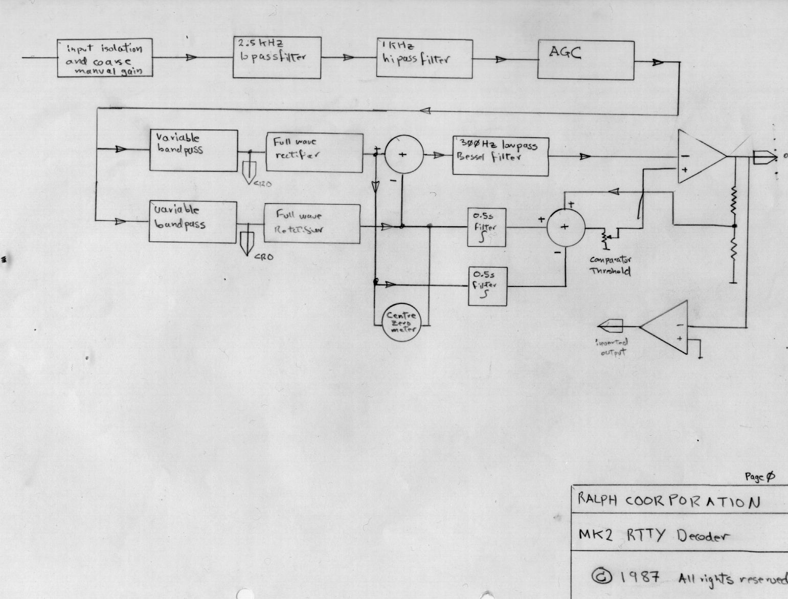 |
My block diagram from 1987. In retrospect the function of the variable
hysterisis and theshold predictor was not properly drawn, in any case it was an afterthought
added a year later. Here is my redrawn ( in Aug 2012) block diagram . Hope it sheds a little more light.
|
 |
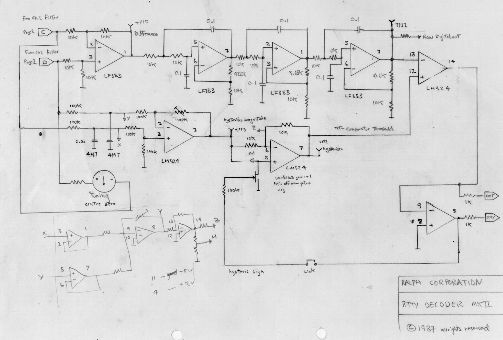 |
| subtractor,
3 stage Bessel filter, slicer, hysterisis feedback
magnitude analog computer. The fet performs the "bi-phase" operation,
whereby the gain of the controller op amp is either exactly one or
exactly minus one depending on the state of the output comparator.
This is actually a kind of programable schmitt trigger, only do
not
tell Mr Schmitt ! After some correspondence from Mr Franklin Brooker
who
requested clarification of this rather inadequate drawing I have
redrawn this circuit from the original hardware. That is after
some 25
years. It is quite hard to do this after so long....what the
devil was
I thinking way back then ! The stated intention of this
complex circuit is to predict the correct comparator A7 threshold for
the next bit transistion. |
 |
| apologies for the 25 year delay in delivering the documentation. |
 |
|
Input audio preprocessing, input amp, low pass and hi pass filter, this
arrangement rejects squeels and mains hum, and a simple but very
effective AGC stage using a fet, precision halfwave rectifier and time
constant set to track long term fading and give the rest of the system
a good set point, that minimises DC base-line wander in the
recovered analog data. VR1 sets the zero signal input quiesent bias on
the fet by adding a constant offset to the time constant buffer output. |
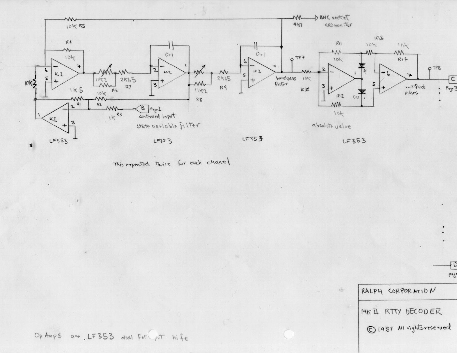 |
This is the variable state filter, and we select the bandpass output,
one for each rtty mark and space frequency. It feeds
a precision full wave rectifier. Notice that the rectifier output is
not filtered, will will leave that to the Bessel filter to recover
every last meaningfull millivolt of analog signal before the last
comparator makes its fatefull decision...one or zero. The state
variable filter design was based on this little article from a very
ancient (1985) EDN. This filter is magic, its gain does not
depend on the centre frequency ! Just what we want for RTTY ! We
use a state variable filter because the centre bandpass frequency is
simple controlled with a dual gang pot. Try that with the
"standard" Sallen-Key filter.
|
|
| Notes for understanding the digital to analog conversion circuit of my decoder, decoded . |
 |  |
| page 1 of 4 | page 2 of 4 |
 |  |
| page 3 of 4 | page 4 of 4 |
| I promise to type this up and make it presentable, but this is the gist of it. |
following on , my design notes to myself...The lesson here is to keep your
notebooks so that you can understand your designs twenty years later !
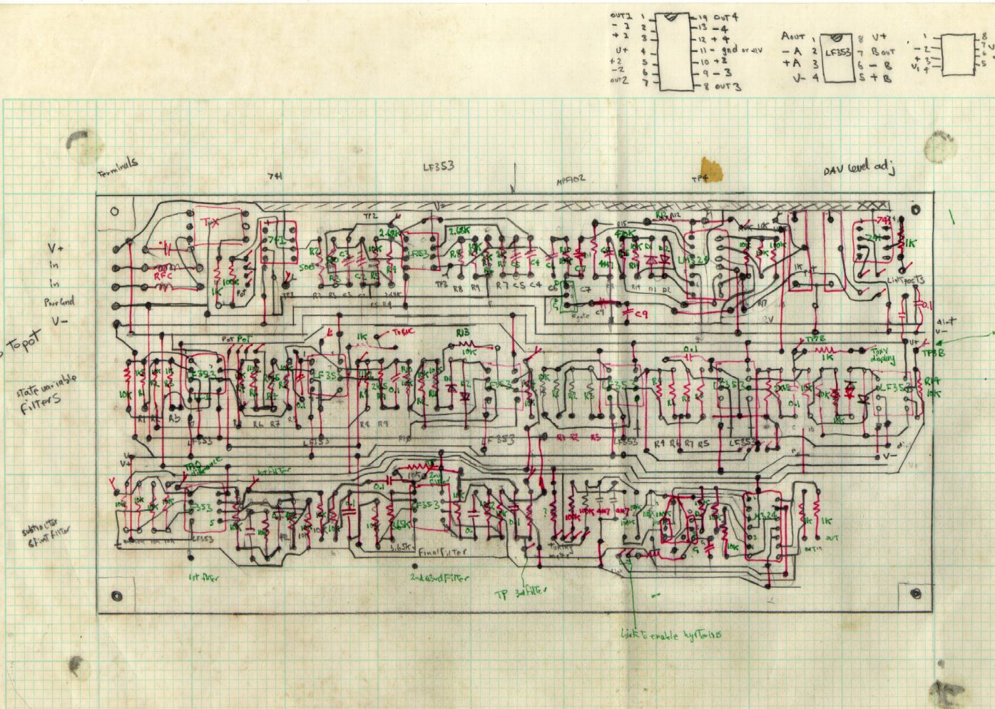
this is a hard way to layout
Traditional photo tool of PCB, and despite the little patent warning it
isnt, the circuit board design tools were like a lettraset rub on and
there was a rub down "protected by US and worldwide patents" with which
one could "protect" your artwork. What a load of cobblers! I
seem
to recall also that the Bishop Graphics artworks materials was also
hideously expensive. ( No it is not patented, feel free to reuse as is, where is.
Homemade PCB with afterthought. The afterthought is now (finally) properly documented above.
copyleft
permission is granted use this information and ideas as you see fit,
attribution would be nice too...the EDN extract , off course, belongs to them.

last update Fri May 9 18:51:28 EST 2008, added more content
Mon
Aug 27 18:23:23 EST 2012 added new content, added redrawn
schematics and more design notes, after numerous requests for
clarification. My apologies for taking so long.
It was a long project after all!