The
Ray 'O Death 803.11b radio antenna
by Ralph Klimek, copyleft 2008,
NO rights reserved! copy as you see fit |
abstract : A simple and high gain reproducible antenna for 803.11b wap hunting and extending the range of 803.11b wireless network cards using a simple Helix. The possiblility of using a WW2 idea "CHAFF" for extending the range of WiFi appliances is discussed. keywords: antenna, helix, WiFi, 802.11b, extending range, chaff |
If you are reading this
then you
allready have need for this and it requires no further justification.
The range of pcmcia type wireless cards is only of the order of 50 to
100 meters using the so called antenna that it bult into these cards.
If you require extra range or you are running something like
Kismet or AirSnort or Netstumbler and you need to know where and in
what direction a rogue wap may be , then you require a highly
directional antenna and one of the very few commercial wap cards that
have an external antenna input.
Commercial 803.11b high gain antennas are generally very expensive. Most of them are yagi arrays. A yagi array at 2.5 Ghz is allmost completely irreproducible and the commercial ones have gone through many many interations to get anything that just barely works. These designs are un copyable unless you can source the exact metalwork. (see also emergency 802.11b wap antenna) This antenna is a bog
standard HELIX.
The helix array is inherently broadband unlike the yagi. The helix
array has just slightly less main lobe gain than an optimised yagi. The
Helix is not sensitive to vertical/horizontal polarization. A
Helix at 2.5Ghz is small enough to be a hand held device. You
do
not want to be weilding a dish in the wind with one hand and
supporting a laptop in the other!
This design is highly reproducible because of the non critical nature of the helix array. Dimentional tolerance of 30% will not materially affect performance more than a dB or two. If you want extra gain just add more helix turns, allthough anything longer than a meter is clearly too hard to walk around with and will make you look like an alien. The design was taken
from standard
Helix formulas from the ARRL radio amatuers handbook. The nominal
impedance of a Helix is about 120 ohms which makes it a
moderately poor match to 50ohms. My hueristic matching
network
consists of running the spiral up from the ground plane at a
characteristic of 50 ohms up to the main pitch of the spiral. My theory
is that this slowly adapts the travelling wave to the impedance of the
spiral, the spiral slowly adapts the impedance of the spiral to that of
free space. The design tables suggest this helix should have
a
gain of about 10dBi and if the indicators in the wap cards
are
even remotely correctly calibrated (which they are not) I measure at
least 8dBi of gain. In practice it is highly directional and
will
associate to a wap that is well and truly out of range when using just
the inbiult antenna.
How long can the helix be? The design is so simple,
so how come manufacturers of microwave dish antennas are still in
business.?
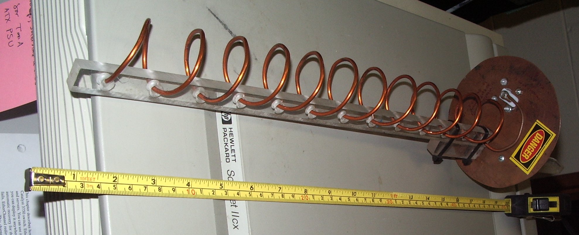
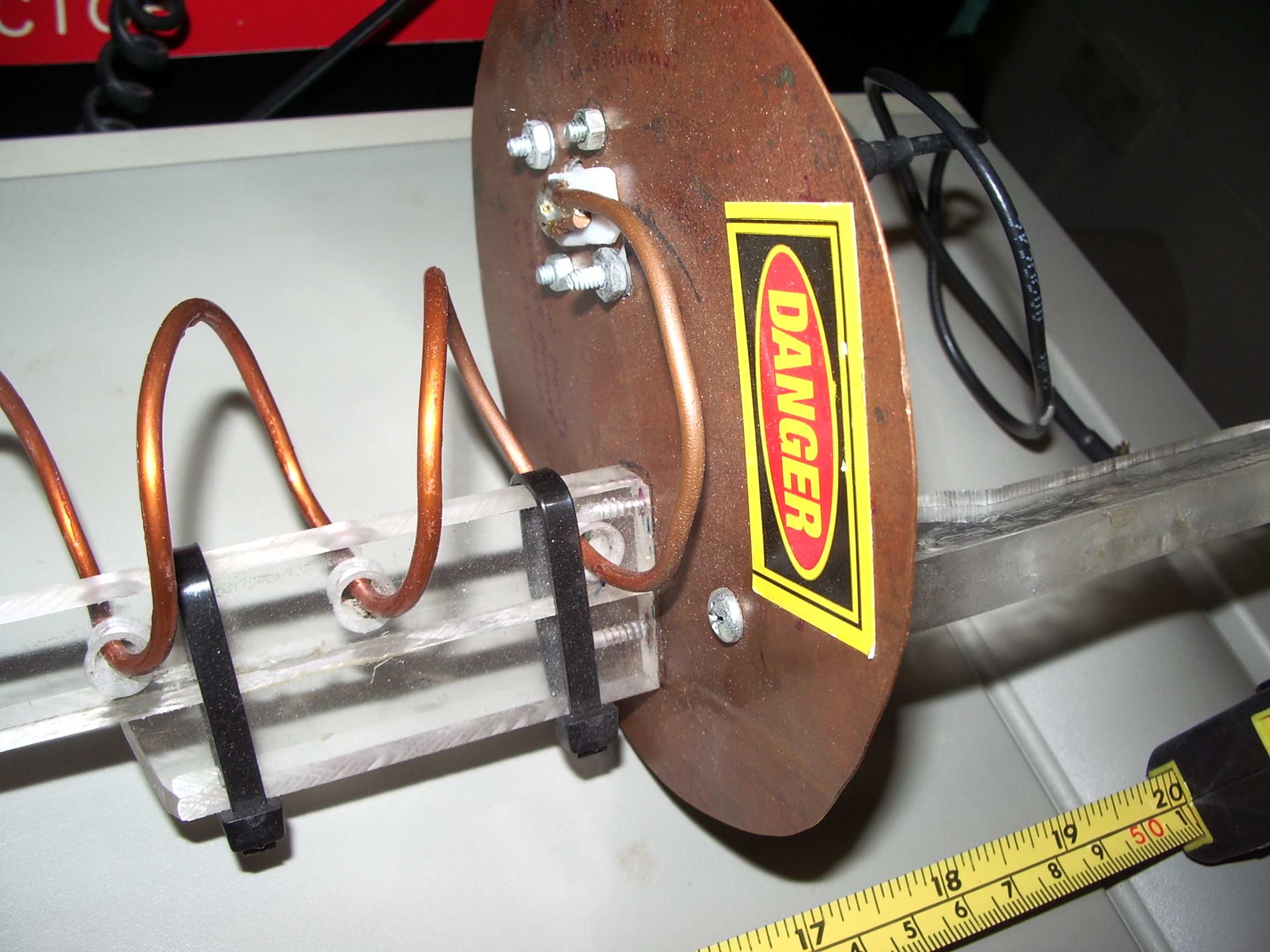
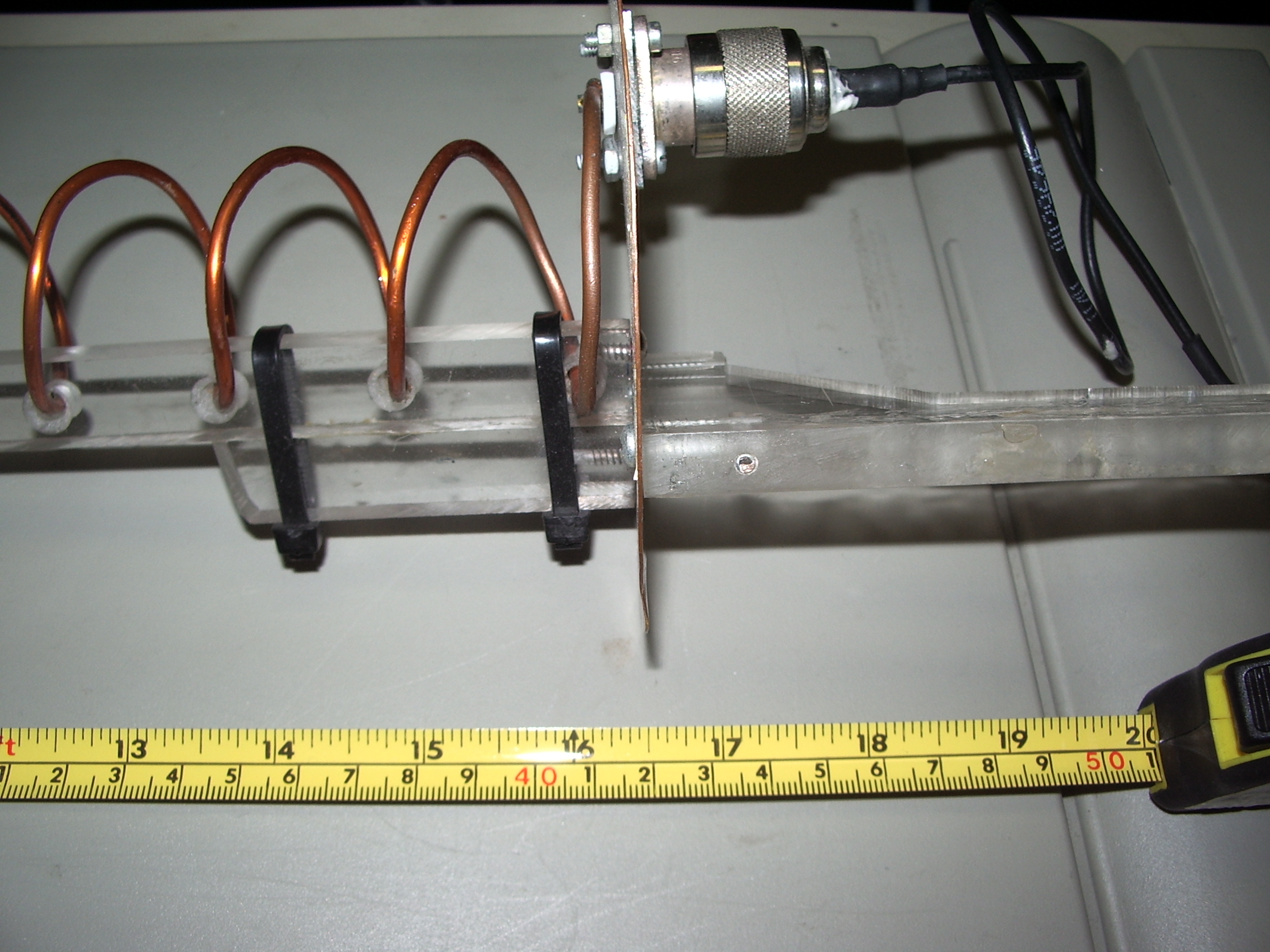
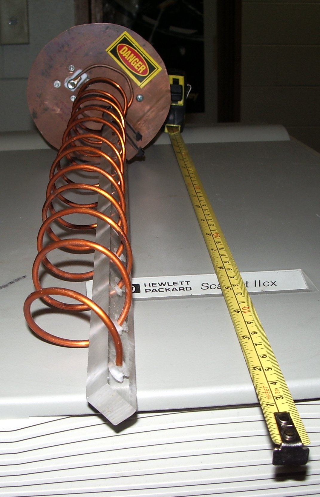
The reason is that the simple model of helix radiation is no longer valid for helix lengths greater than about 7 wavelengths. This would make a the maximum realistic length about 85cm beyond which there would be no further gain increase. It might be possible to progressively change the helix pitch but this is hard to do in practice and difficult to model in programs like mininec. The only acheivable way of further increasing helix gain is to biuld a stacked array and use a power combiner, but phasing becomes very diffcult and a stacked array is hardly a hand held device! Above 15dBi, a dishy makes better sense. Materials The spiral is heavy gauge copper wire, use the heaviest gauge you can obtain as this reduces loss and keeps the bandwidth high. The spiral is supported on a perspex rod and the handle was cut from the same sheet of heavy perspex. The groundplane is a sheet of copper recovered from a dead hot water service. Double sided PCB material would also be suitable. The spiral is soldered to a type N connecter mounted on the ground plane. Now you have to find the pigtail suitable for your wap card. This is hard. The pre terminated pigtails are hard to source and each wap card uses a proprietary miniature microwave coaxial connector which are nearly impossible to source. For this I have no advice. Older wap cards had a hollow moulded shroud over the antenna which could be removed with care and it was possible with great care to solder sub miniature coax onto the antenna feed. Some wap cards have the coax connector hidden with a plastic dummy. Dlink are known sell an external antenna accesory for their wap cards. |
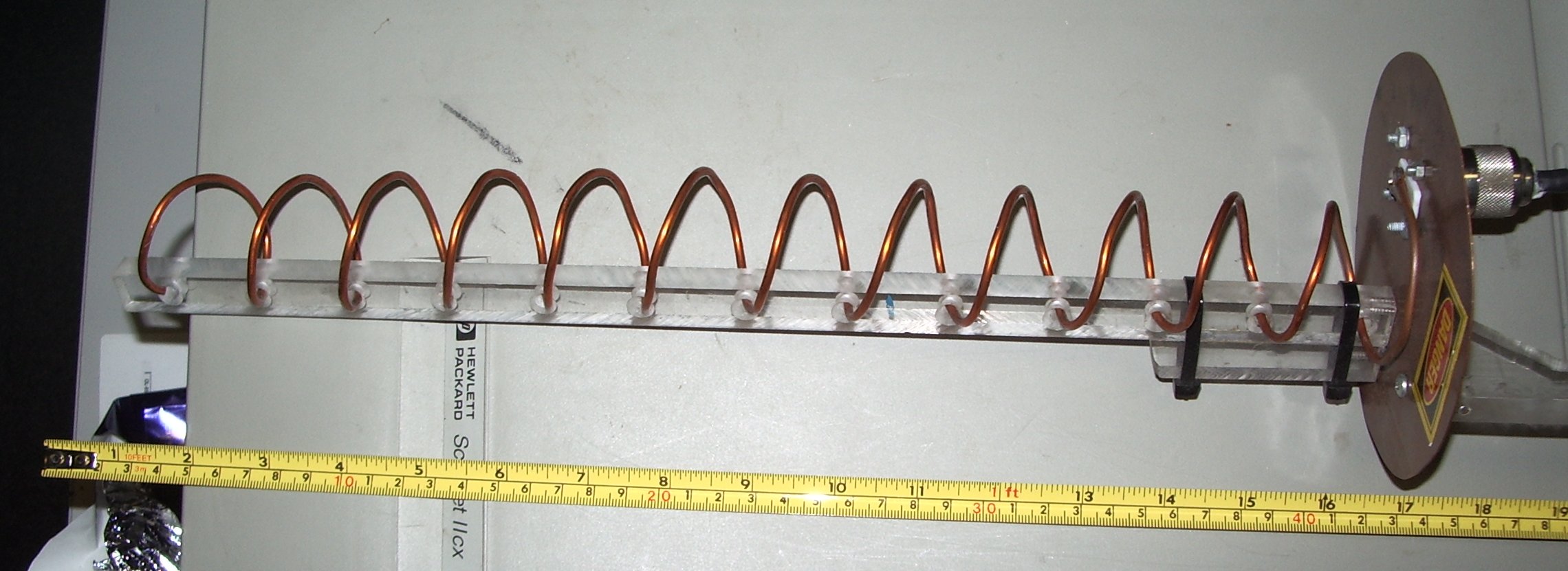
| So here it is, the Ray 'O Death . | |
|
|
|
|
|
blank |
|
|
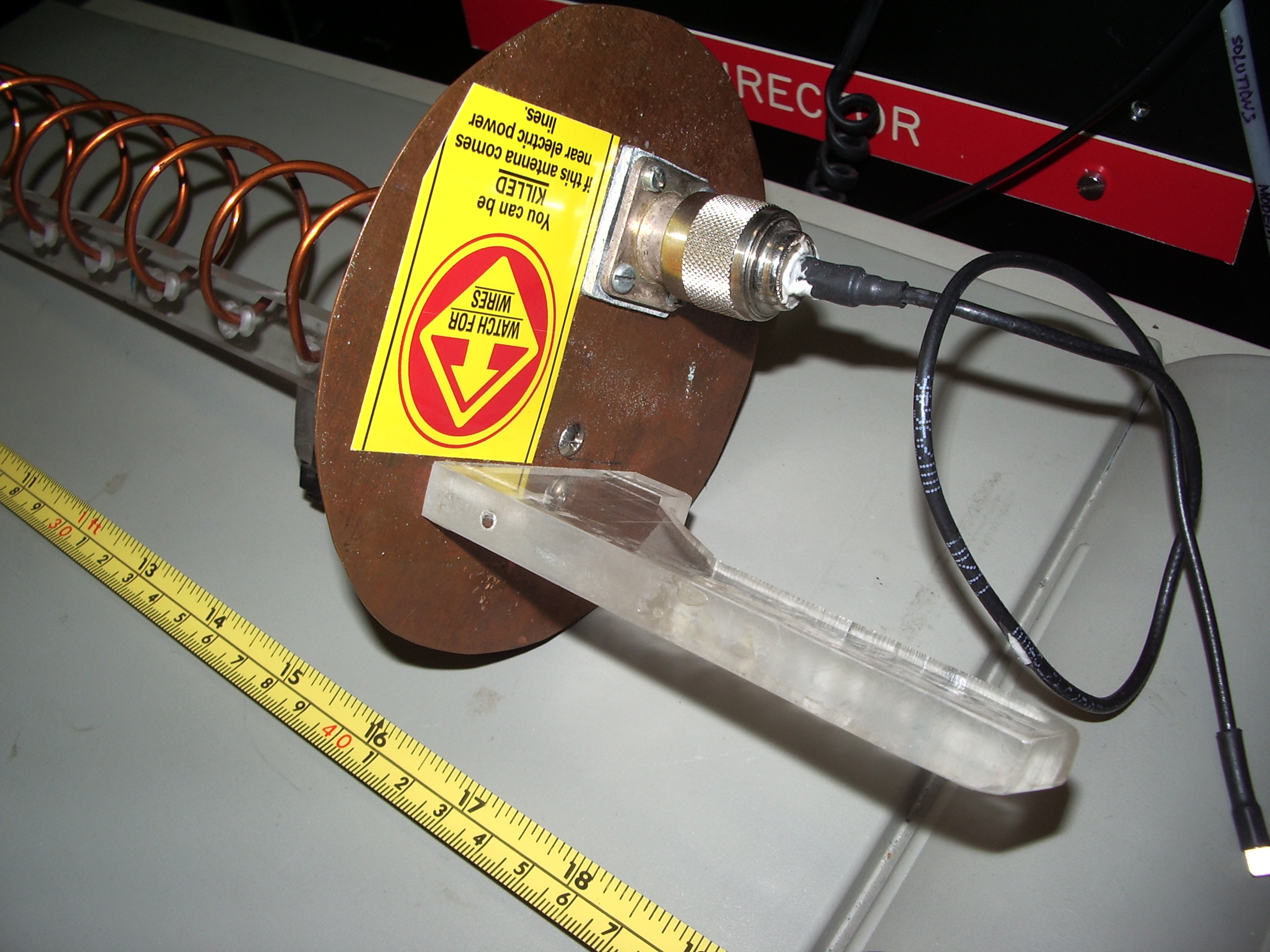
| Detailed
dimensions are not given because they
are not needed. "About right" will be right! , However, the radius of
the ground plane should be one quarter wavelength. See also
standard radio textbooks for general rules of thumb regarding
dimensions. The ARRL radio amatuers handbook is the best reference for
DIYs. |
|
| An emergency 802.11b wireless access point wap antenna | |
| this
was an emergency wap antenna that I constructed out of the coax
emmiting from the bottom of this house. The big TV antenna mast was
blown onto the ground taking the external wap antenna with it.
Someone had come along and cut the coax which now
was a trip hazard. I had come along to discover whey the wap
was dis-functional. The coax was good quality double shielded
material, the wavelength was about 10cm ( at 2.540Ghz)
So, with nothing more than a pocket knife I made this
"bozooka fed half wave dipole". The outer-outer braid layer
was folded back and cut to be a notional 1/4 wavelength which
forms a choke. The "dipole" occurs with the inner
braid and the centre conductor. The choke permits the exposed
inner braid to become a half wave dipole element. Did it work ? ...yes....! |
|
 |
 |
 |
 |
| Chaff chaff for 802.3b WiFi networks? |
| A cheap technigue for making
marginal improvements in wireless access point coverage using passive
repeaters |
Chaff was one of the great secret weapons of world war two. It consisted of nothing more than strips of metal cut to one half wavelength of the radar centre frequency it was meant to jam. Jamming was not its intent , or ability. It merely provided multiple source of radar reflection, sufficient to confuse the enemy airforce controller /despatcher. A piece of resonant chaff could give a larger radar cross section than the target enemy plane, the real target would still appear on the radar scope along with hundreds of echoes from the chaff. I have a new shed and my 2.540Ghz access point is now allways up. The shed is about twenty meters away from the access point, there is a new house wall with metal foil thermal insulation in the way. What hope was there for a laptops 803-11b wapcard to work in the shed ? Not much, but sufficient backscatter from assorted objects and the fact that real metal sheds have sufficient gaps that some 10cm microwave radiation could find its way in and also out. The best network connection thus acheived gave only a 1mb/s connection and was very unreliable. I was about to discard a useless piece of metal flashing when I thought about chaff. I cut the flashing into strips 6.1 cm long and about 1 cm thick. I cut out about 20 such pieces and scattered them at random about the property and inside the house roof space. My thoughts were that multiple scattering centres would be provided, think of "passive repeaters". Would the resultant multipath signal reflections render the idea void ? The result was that I now have a reliable full speed wireless lan network connection inside the shed, via a microwave path that is clearly NOT line of site. iwconfig reports 11mb/s connections where previously only 1mb/s connections were possible. I do not posses equipment for measuring field strength at this wavelength but with the existence of more possible paths, and the non linear capture effect in digital radios, the dominant path would prevail. If the "dB" measurement that some rarer WAP cards can return are to be beleived at all, then I had improved the average signal strength by maybe 3 to 5 dB which for WiFi connections can make the differance of having or not having a link. Material is not critical, but common sense would suggest copper or aluminium, I used zinc plated steel strip only because that was the material at hand. The better passive repeaters have a nail through the middle so that the dipole stands well away from obstacles like wall and can be nailed to something. Nail them up in your roof space and see the differance they make. But wait there's more! I can attest that chaff cut for 1800 Mhz mobile phone band works wonders. It will deflect tower signals into poorly illuminated areas inside biuldings and will extend mobile phone coverage into areas, otherwise , that cannot get a functional connection. I have used it both at home and work to improve mobile coverage from barely useable to useable by scattering half a dozen around the place. |

