a directional coupler for HF and lowband VHF
by ralph klimek VK3ZZC
April 2016
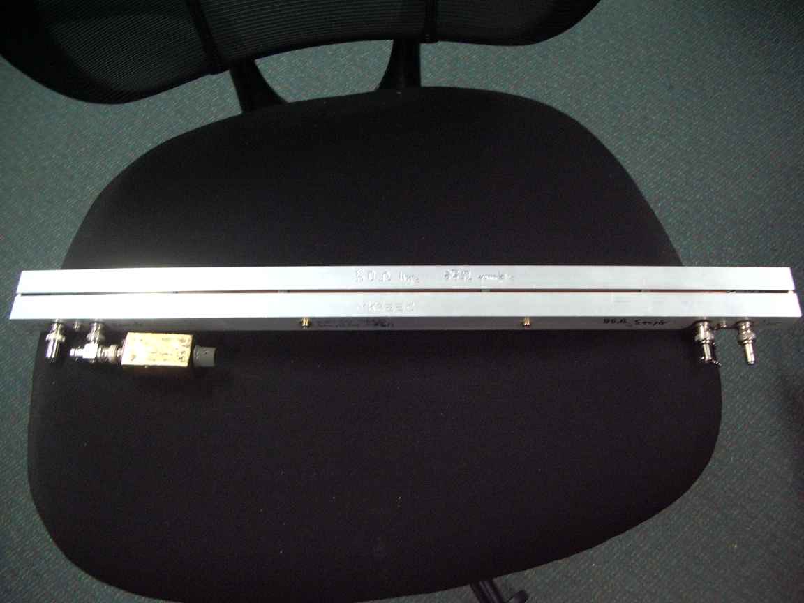
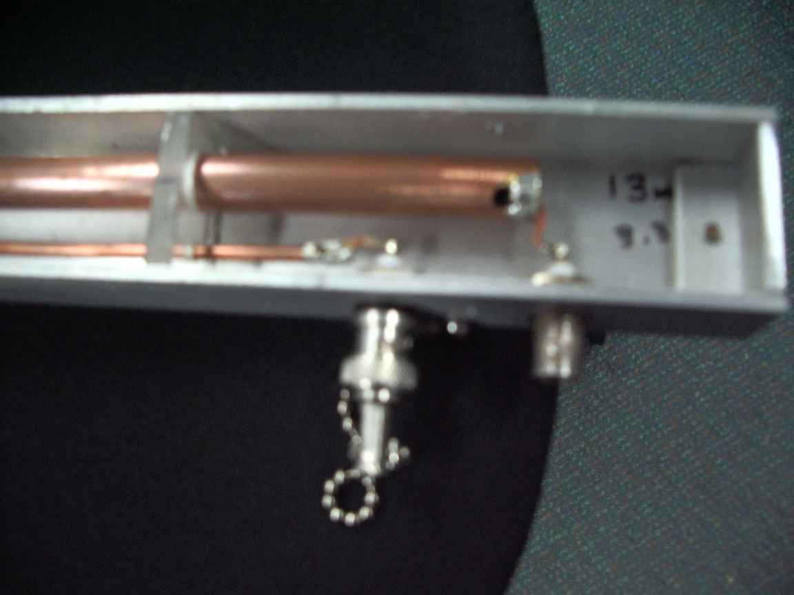
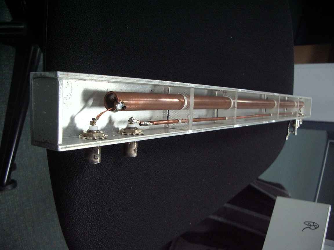
The construction is somewhat reproducible because it uses commercial off the shelf (COTS) metal extrusions and standard components. By some wonderful coincidence the theoretical impedance of the main line would be within 5% of 50 OHMS. However, that came from a table of standard line section impedances that cannot take into account the disturbing effect of the sampling line and the slot. The sampling line also requires accurate termination before meaningful measurements can be acquired. Determination of the sampling line impedance from tables is fraught with danger due to the disturbing effect of the mainline. This sampling line would have to be calibrated somehow. I made the deliberate choice of COPPER for the line elements. This was chosen soley for the ability to solder the electrodes to it. My original slotted line apparutus suffered somewhat for the inability to make good electrical connections to aluminium.
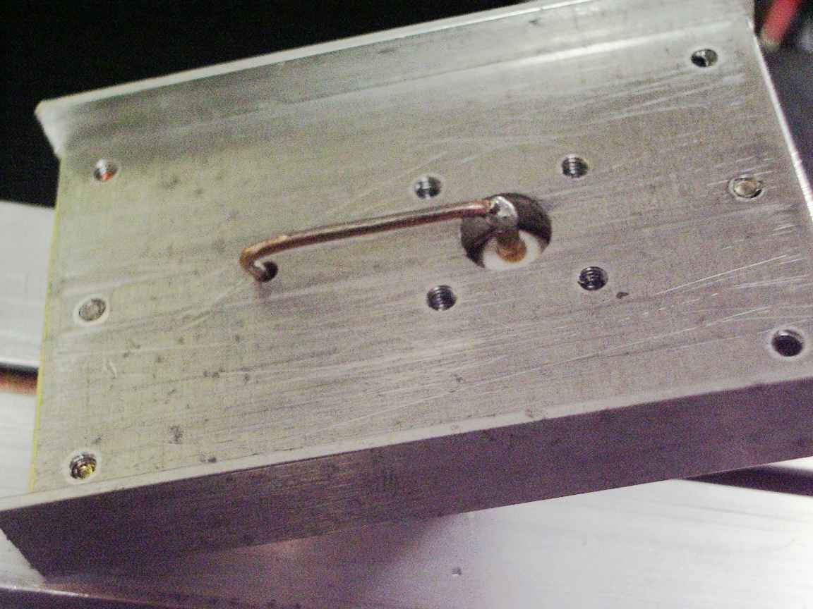
The top cover of my coupler was originally intended to be completely covered to eliminate the slot. The slot is an unwanted artifact of having to use commercial off the shelf extrusions which allways conspire to be the wrong size ! But now I have second thoughts. The precision of my perspex sheet insulators was sufficiently good that maybe the slot could be used as the slot in a slotted line apparutus for UHF. Why not ? I do like slotted lines having made a really nice one about thirty years ago and long before played with Lecher Lines for frequency measurement in the days before I had biult my DFM. Yes, indeed. Next little project will be a inductive probe and slider arrangement. The perspex insulators will need a little slot cut for the pickup loop. Later I did precisely this. See below.
What I really needed to calibrate my line was a vector voltmeter. One day, I hope, the Great Cargo Gods will leave a HP vector voltmeter for me in a dumpster somewhere, stranger things have happened. But, in the meantime...
Calibrating my coupler.
It can be done without a VNA or vector voltmeter ! Heres How !
This method absolutely astonished me, that it was possible with using nineteen seventies vintage equipment that had been scavanged from dumpsters and flea markets. I had a early 70s vintage pulse generator and a 100Mhz scope. The pulse generator was easily repaired as it used only discrete components. It has a believeably good rise time specd at 5 nanoseconds. It used a tunnel diode pulse shaper. Remeber tunnel diodes ? Probably not as they became a forbidden technology along with the Backward Wave Oscillator. (Paranoid, delusional conspiracy theory warning !) in the 80s. Could I use time domain reflectometry to calibrate my coupler ? It is a big ask. I have to be able to observe the time of flight of light itself along the length of the coupler. It is only half a meter long, the time of flight is only about 2 nanoseconds. That is not a lot time !
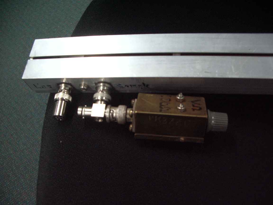
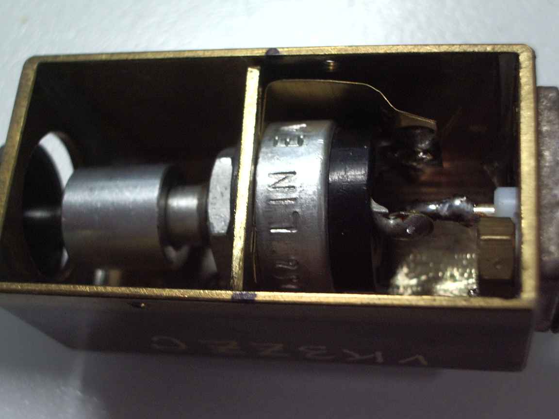
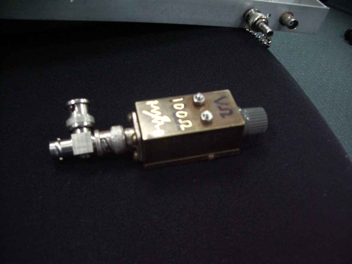
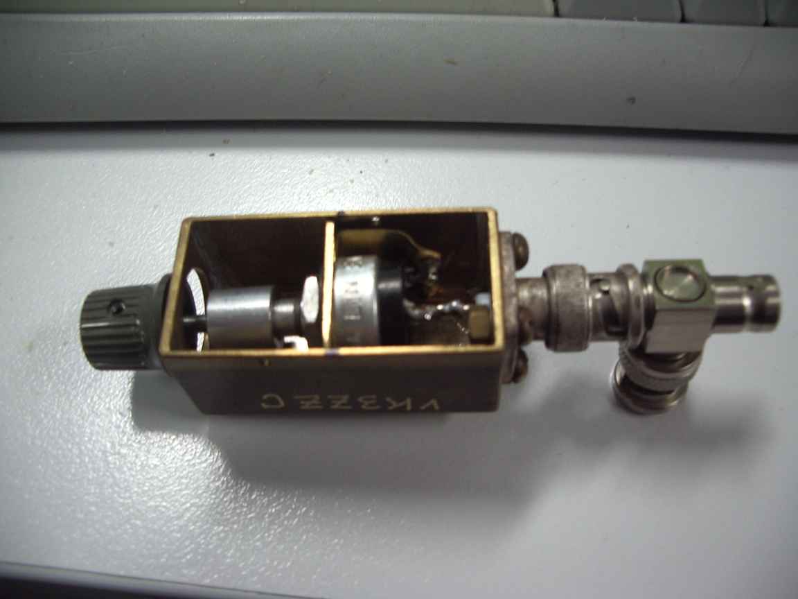
In the TDR principal, I have to launch a well formed pulse, trigger a scope, the pulses' leading edge travels to the remote end of the line, is reflected back along the line and is absorbed in a 6dB attenuator after being displayed on the scope. Would this remarkable signal be visible/discernable on my primitive equipment ? It was ! If the reflected pulse was to be absorbed by the CORRECT termination then there would be NO reflected pulse as mandated by the Laws of Physics. In my workshop, we obey those laws. Thus was born my precision variable resistor. It is nothing more than a 100 ohm carbon miniature pot mounted in a nice little brass box that was also salvaged from a dumpster at work. All internal connections was performed with large sections of brass shim stock to minimise as much stray reactance as possible.
All I had done was to observe the reflected pulse dissappear at the pot was adjusted. When satisfied, the pots resistance was measured. Bonza, it said my main line was 52 ohms and that is close enough. To confirm I replaced it with a precision 50 ohm terminator and the reflected pulse vanished.
Now to calibrate the sampling line. That matters just as much as the main line. One end of the sampling line must be terminated in its impedance before we can seperate the forward and reverse energy flow components on main line.
The sampling line was calibrated by sending pulses down the correctly terminated main line and now monitoring the sampled pulse with the scope. The sampled pulse would also now run back and forth along the sampling line. When one end is terminated in my variable resistor we adjust it to eliminate the reflected pulse. It measured 85 ohms in my device. I then made a precision terminator with a metal film 82 ohm (closest resistor in my cabinet) in a crimped 50 ohm BNC crimp plug.
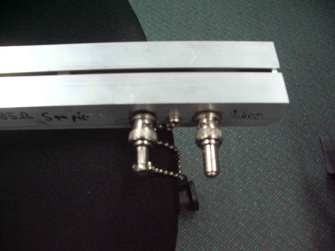
With my terminator applied, the pulse reflections vanished in the sampler. To be sure, I now attached a little chain to it so that it does not go on an unauthorised expedition !
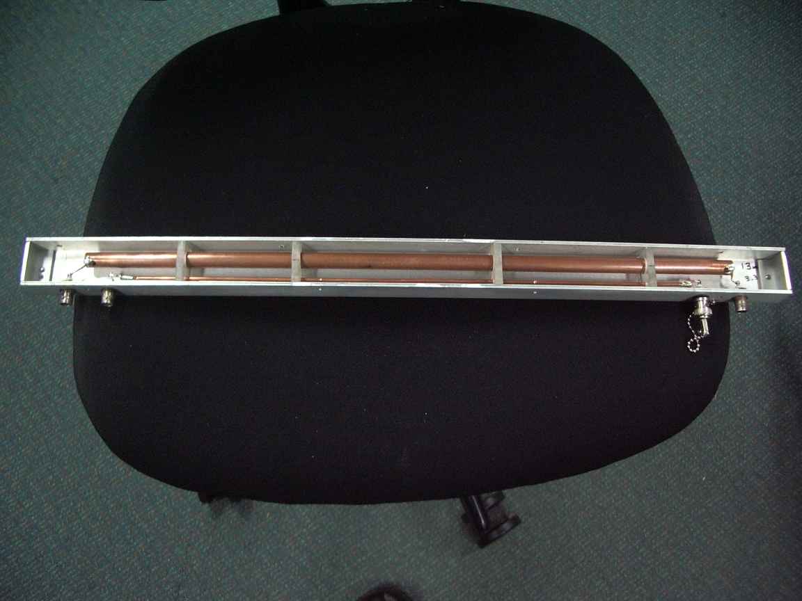
My sampler is now complete. I will document the dimensions of this thing. It uses standard extrusions for all lines. You might have trouble getting copper line for the sampler. Mine happened to be 1/8th inch pipe. This may be hard to source but you might find that a length of silver bronze brazing rod is just right ! The inner line was 1/2 inch copper water pipe. The perspex spacers should be spaced in a non uniform way so that the impedance disturbances caused by it do not add coherently.
In any case, do not attempt to make one of these things unless you are able to calibrate it. There are two many variables in construction that would render a like for like reproduction dubious.
Still needed to be done, calibrating the line to line coupling coefficients for various target Amatuer frequencies. This will make the basis of my own Vector Network Analyser on one impossibly distant future day.
Variable resistors of 100 Ohm of this kind are now extremely difficult to locate. Nearly all of them are wirewound which is totally unsuitable for this application. If you see one at a hamfest do snap it up. These days only 1Kohm and above are still manufactured.
Material dimensions are
U Section extrusion is 20x40x3mm
Slot cover is 20x20x1.5 mm
which are standard extrusions
Copper pipe is a length of hard drawn 1/2 inch standard pipe.
Sampling line is 1/8 inch hydraulic copper pipe. Brazing rod would do just fine.
Main line placement is actually not that critical, neither is the sampling line as we will need to calibrate it anyway.
Insulators are made from perspex scrap.
Update ! Newflash ! Stop the Tinternet !
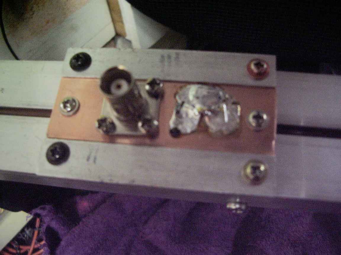
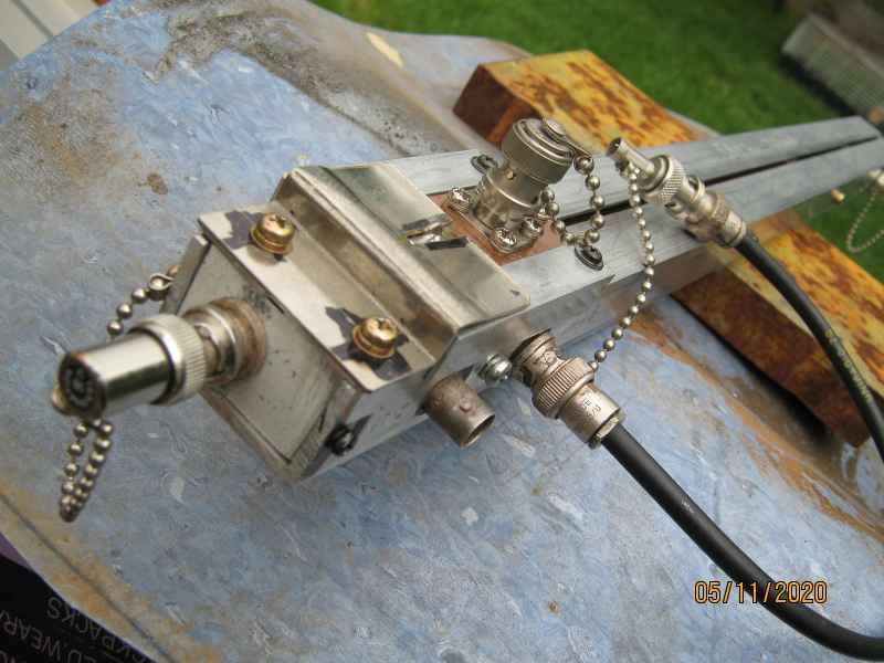
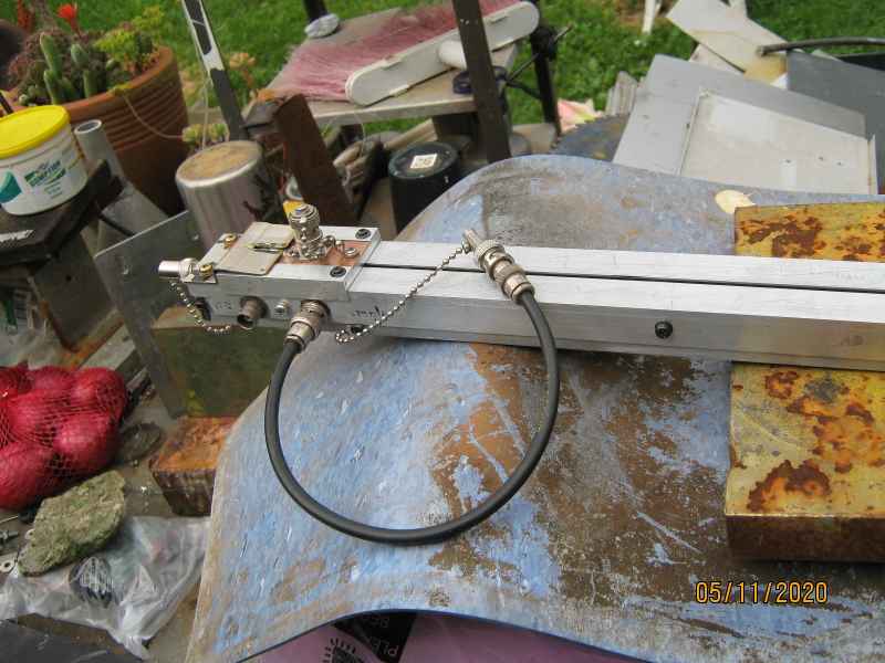
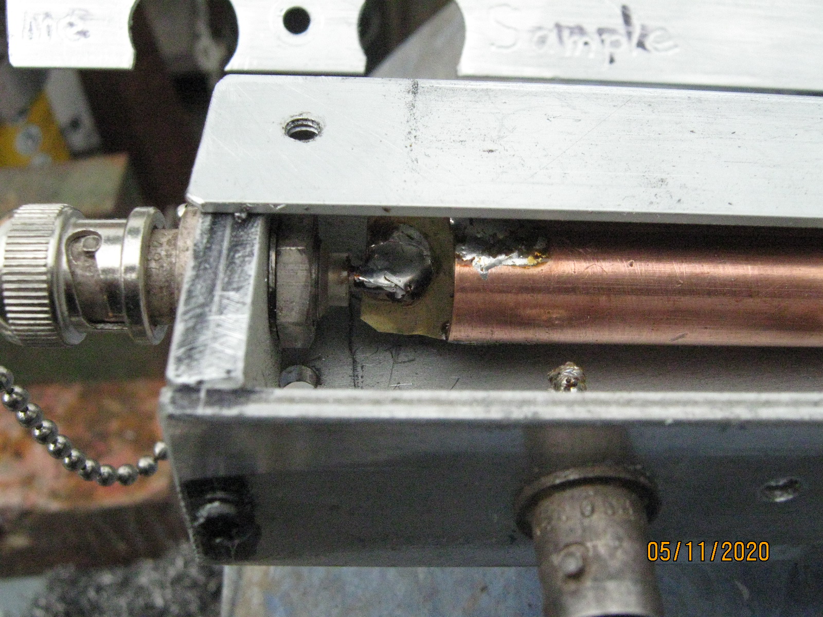
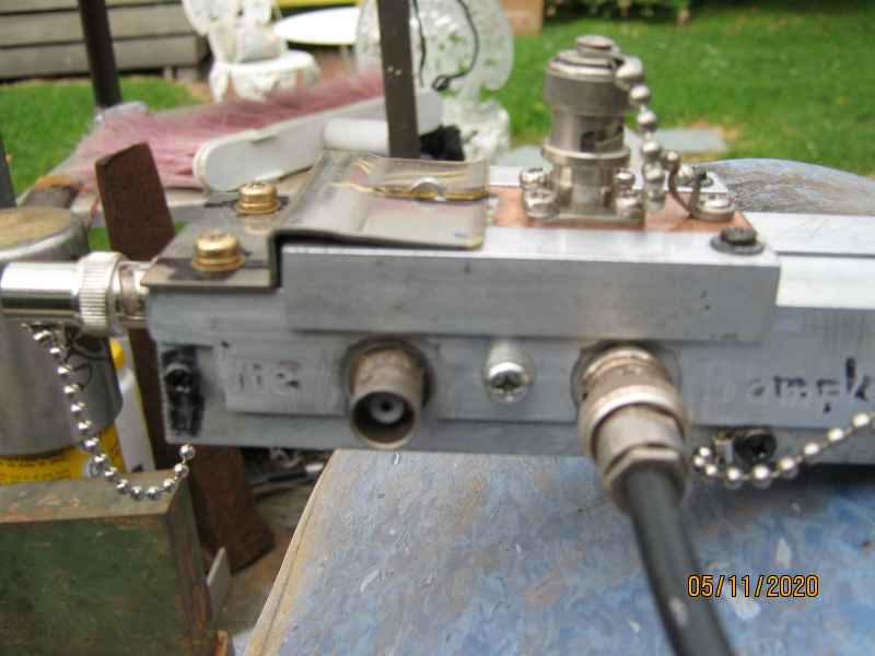
I have modified my coupler. You can see in the pictures, that the input and output ports are rather clumsy. The connections are made with only a bit of thin braid. The impedance of this bit of twirly braid made this ineffective as a slotted line apparatus. I found a longer length of copper tube and have extended it to the ends of the housing, where now decent RF connections have been made to the copper conductor and the BNS centre pins with the medium of brass shim stock. There is affixed to the housing a springy brass sheet keeper for the proble slider assembly. It makes a satisfying click when the slider is stowed in the brass click. I have also made a delay line. This line has the time delay of the probe line. This is to equilize the delay so that I can use it my recently aquired HP vector voltmeter. I really should have a line stretcher for this . I have only once seen a pulse stretcher for sale at a hamfest, dilly-dallied, and lost it . Someone smarter than me snapped it up ! Bolloks.
The pulse delay line is also attached with a little chain. I have found it good to chain little detachable accessories as they allways grow feet and march off into the world, without even the courtesy of saying goodbye.
The coax has been cut to match the propagation delay of the sample line. We first measure the velocity factor of the coax and cut to length. the vf is measure by finding the 1/4 resonance with a grid dip oscillator with a long length of the same coax from the spool. The longer the measurement, the greater precision. The finished assembly is also chained down to stop it wandering. 75 ohm cable was used, this is a moderately good match to the 82 ohms of the sample line. It is a good as it gets, they dont make 82 ohm coax !
homepage

