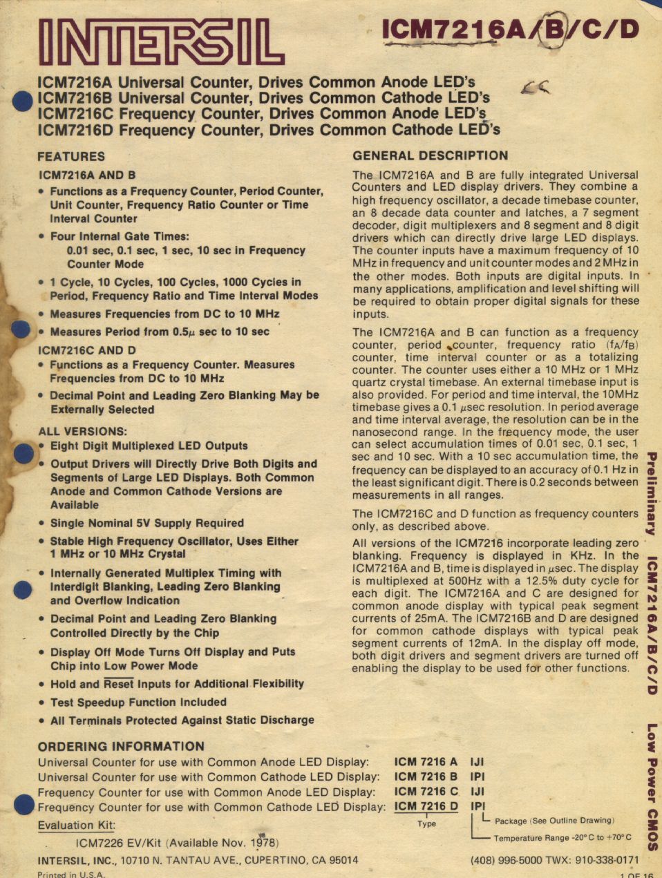
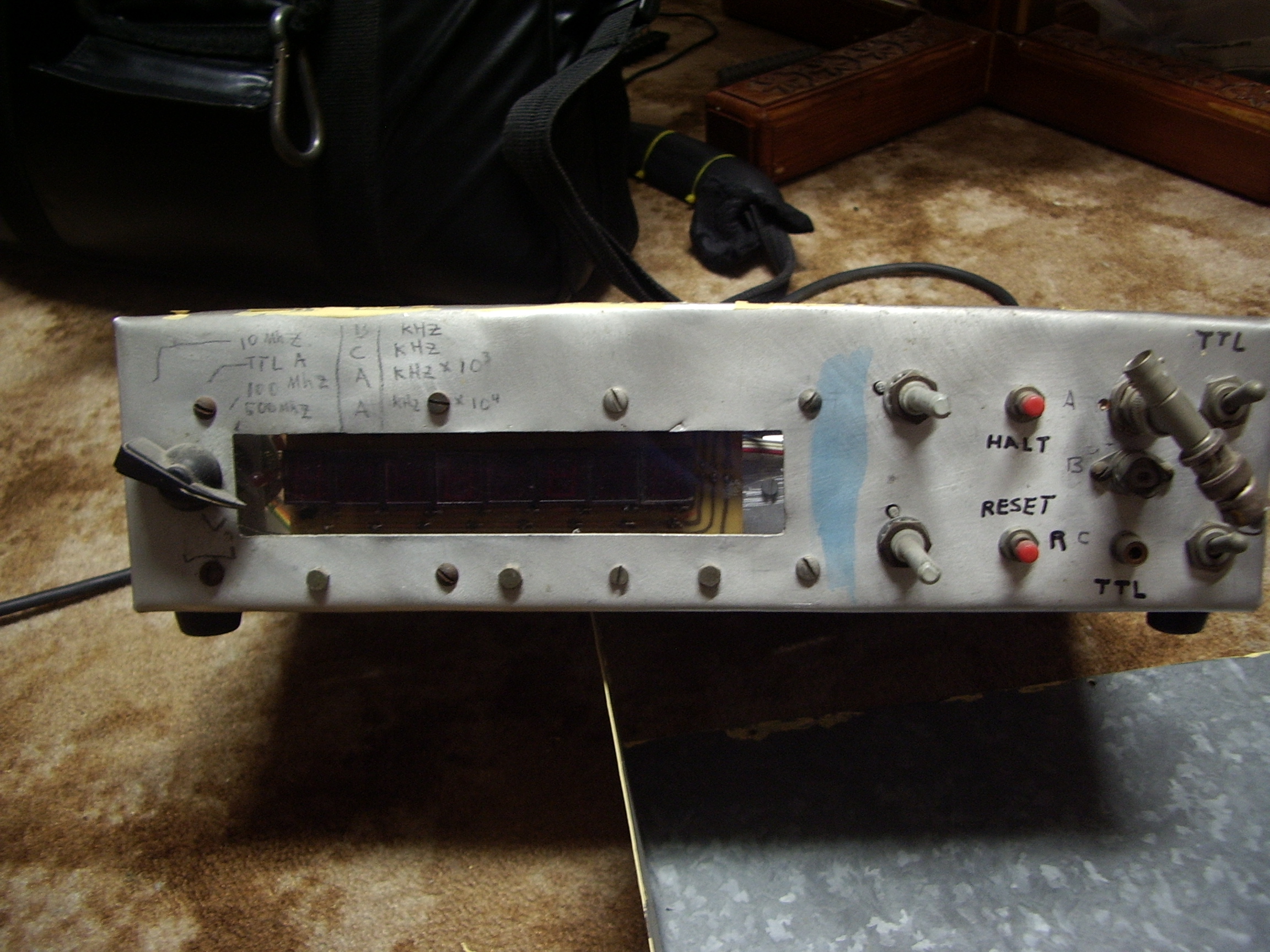
A frequency counter
using the venerable but now unobtainable
Intersil
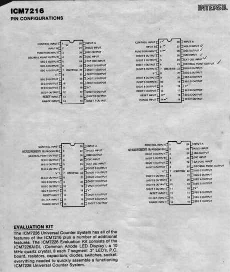
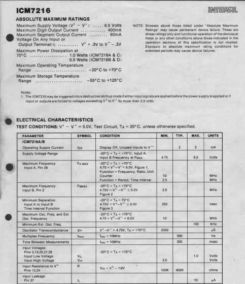
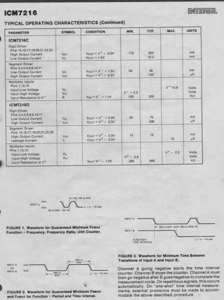
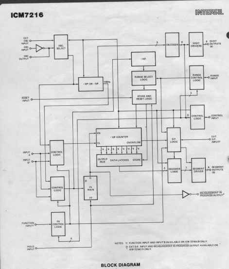
ICM7216
This project was started in 1979 by a fellow student at Caulfield
Institute of Technology who had bamboozled me into buying this (then)
amazing chip from him for $40. The project was eventually
finished in the last half of 1980 and has been a cornerstone of my
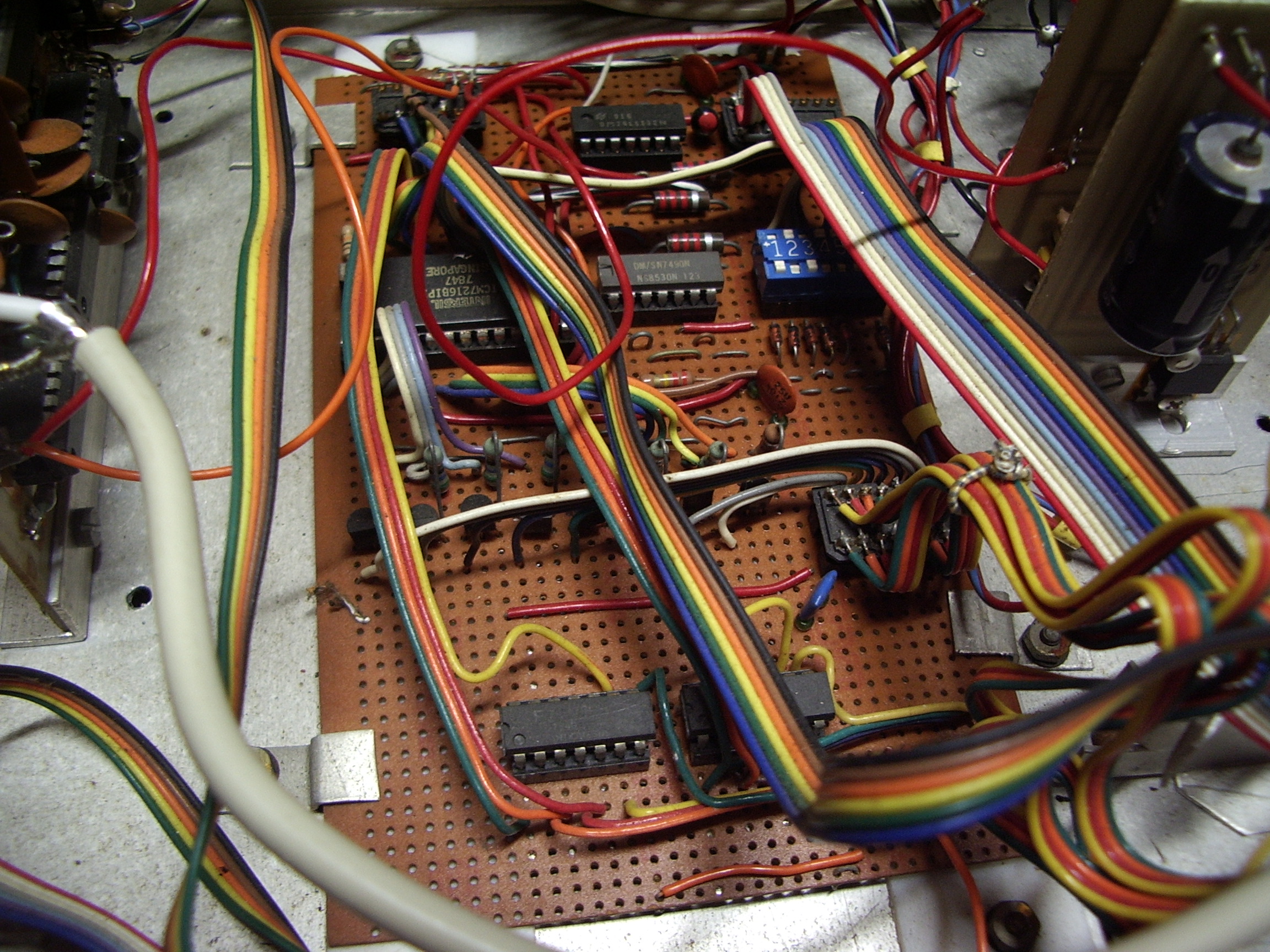
radio home brewing since then. The construction is primitive to
say the least but it does actually work. It was totally scary
powering the thing up for the first time. That Intersil chip cost
me several weeks' pocket money and I was somewhat afraid that a wisp of
smoke would waft out to mock my impudence. To be sure, it was unheard
of in the late seventies that a complex cmos chip should be expected to
directly drive a LED display, because after all, 20mA was a
substantial amount of current for a complex chip. Being terrified of
over driving it, despite the Intersil reference design showing that
LEDS could be directly driven, I still choose to use buffers, and in
retrospect, that was a wise choice. Not very many of my earlier
projects have survived 40 years, let alone still work!
I have long since lost my original hand drawn circuit, so you will just
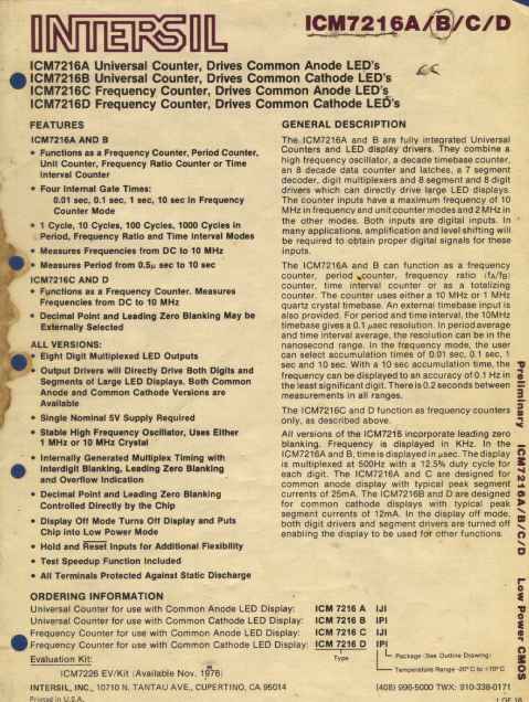
have to believe me. The original Intersil data sheet is presented as
is. Intersil has long since ceased to be despite some excellent
products and helping introduce the merits of CMOS LSI to a skeptical
marketplace. This data sheet does not appear to be present on any
boat anchor or data sheet archive site. It is still possible to
find this chip and some variants in discarded equipment that contained
counters and led displays.
This chip also featured in many electronics magazine projects in the early eighties.
Things I would have done differantly.
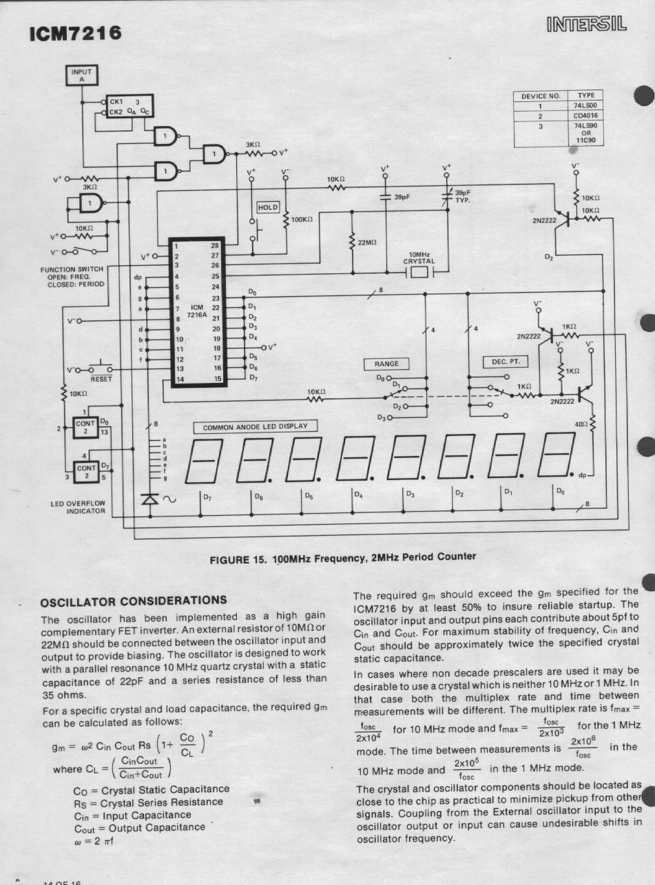
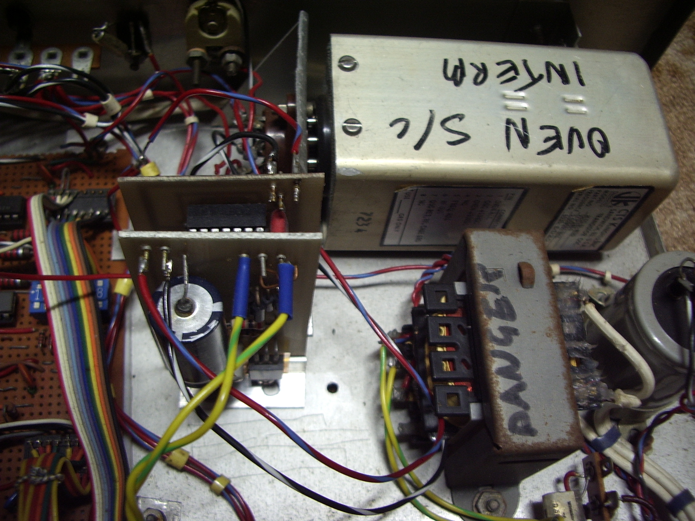
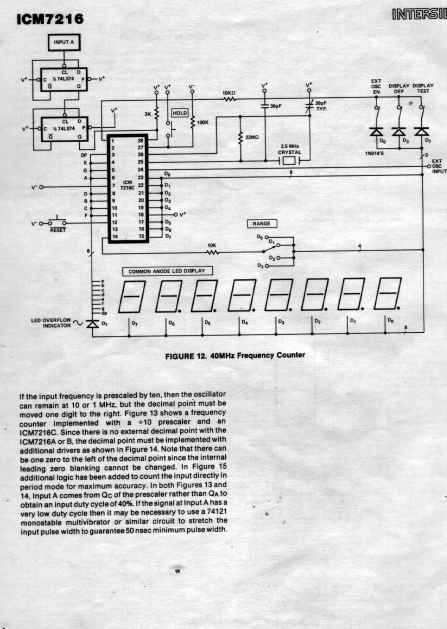
This
chip could have had a 10Mhz timebase. My oven controlled crystal
worked at 5Mhz, so I divide it down to 1 Mhz. The result is that
the non adjustable decimal point is displaced one place.
In
retrospect, I should have used a simple frequency doubler and squaring
circuit which would have had the original stability of the 5Mhz
timebase. Maybe one day I will do just that ! This would give me then a faster aquistion time as well.
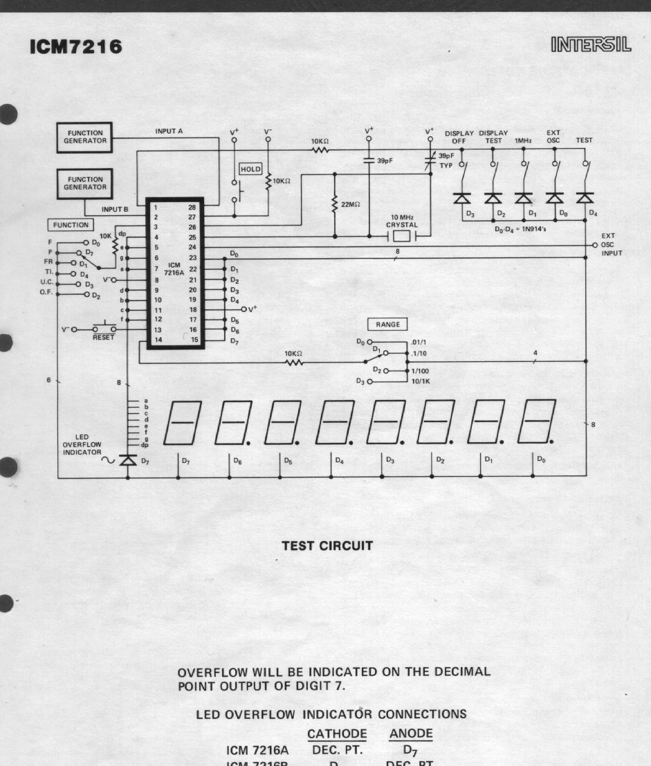
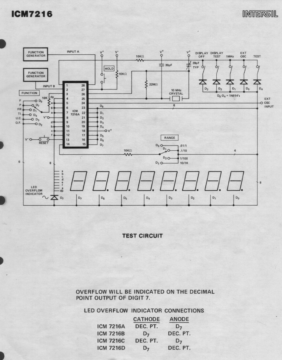
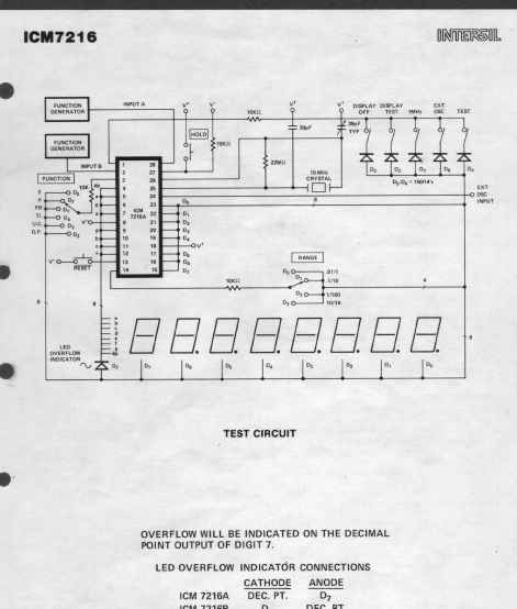
| Intersil datasheet for the ICM7216 8 digit counter |
 |  |
 |  |
 |  |
 |  |
 |  |
 |  |
 |  |
 |  |
 |  |
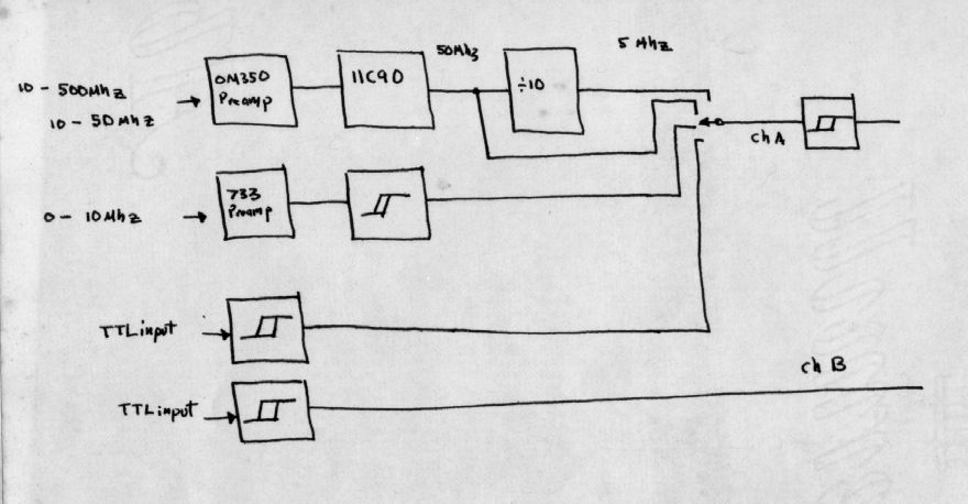 | 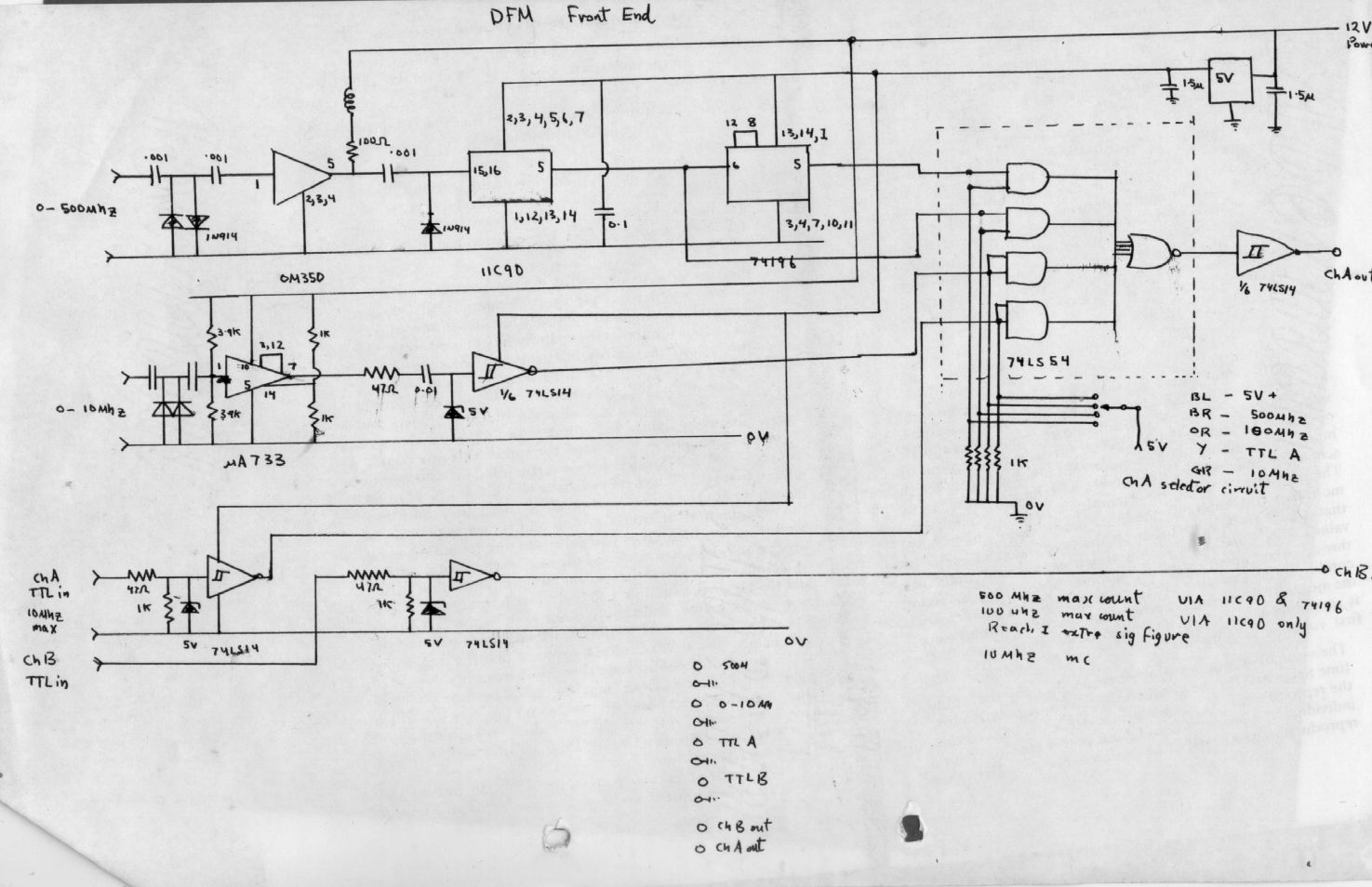 |  |
| block diagram of input prescaler board | The
ICM7216 could only accept input speeds not exceeding 10Mhz so this was
my front end, using an OM350 hybrid UHF amplifier and an 11C90 UHF
prescaler. I remember handing over something like $50 for this
one chip in 1982, they were not rare just amazingly costly, but they
could count up to 600Mhz which seemed amazing at the time. I remember
that when I had bought this chip , I distinctly felt like I had just
been mugged. $50 and all I got was this little white paper bag with
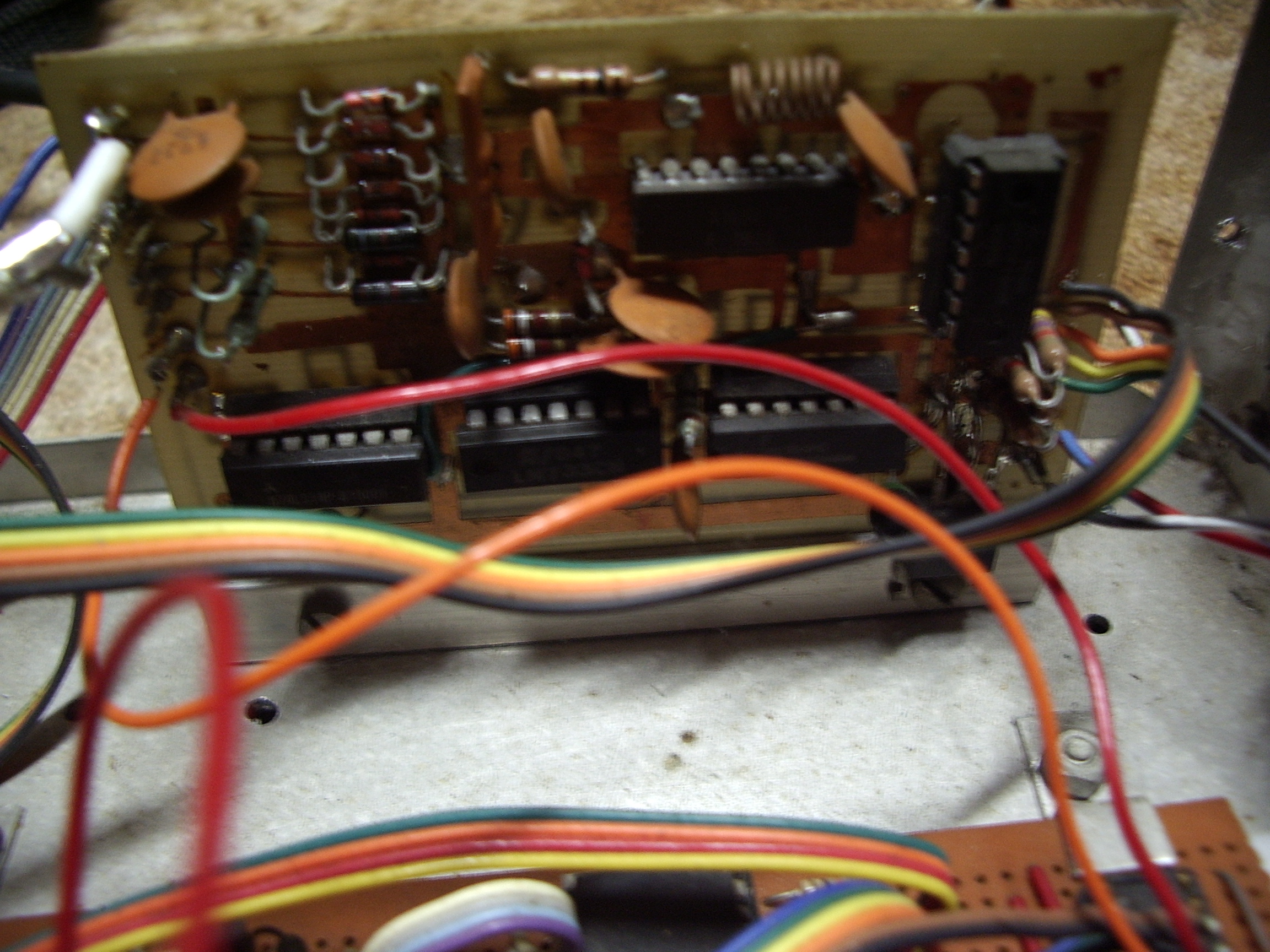
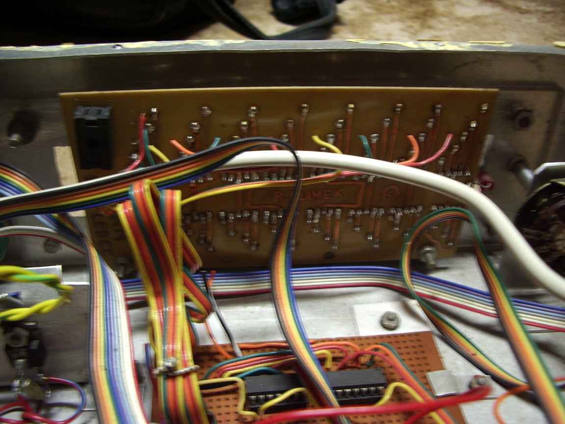
just one little chip in it! | layout of main board and jumper schedule |
homepage

fixed formatting and layout Thu Mar 31 18:56:38 EST 2011