The
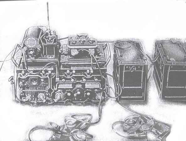
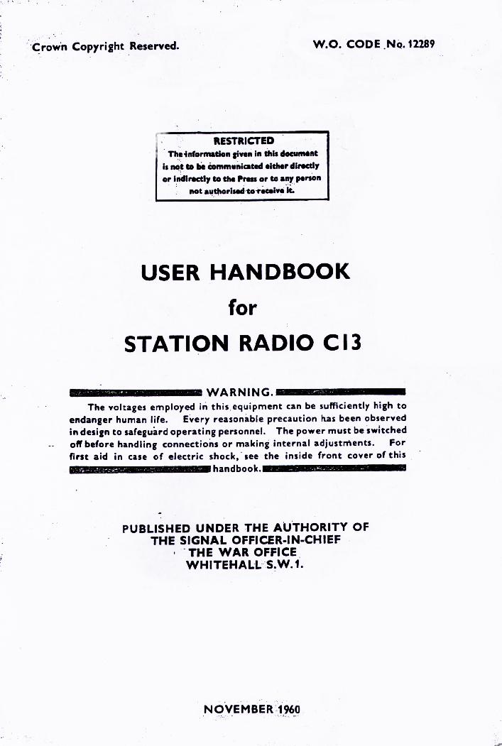
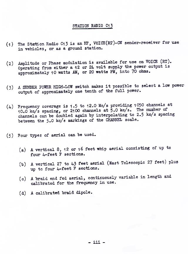
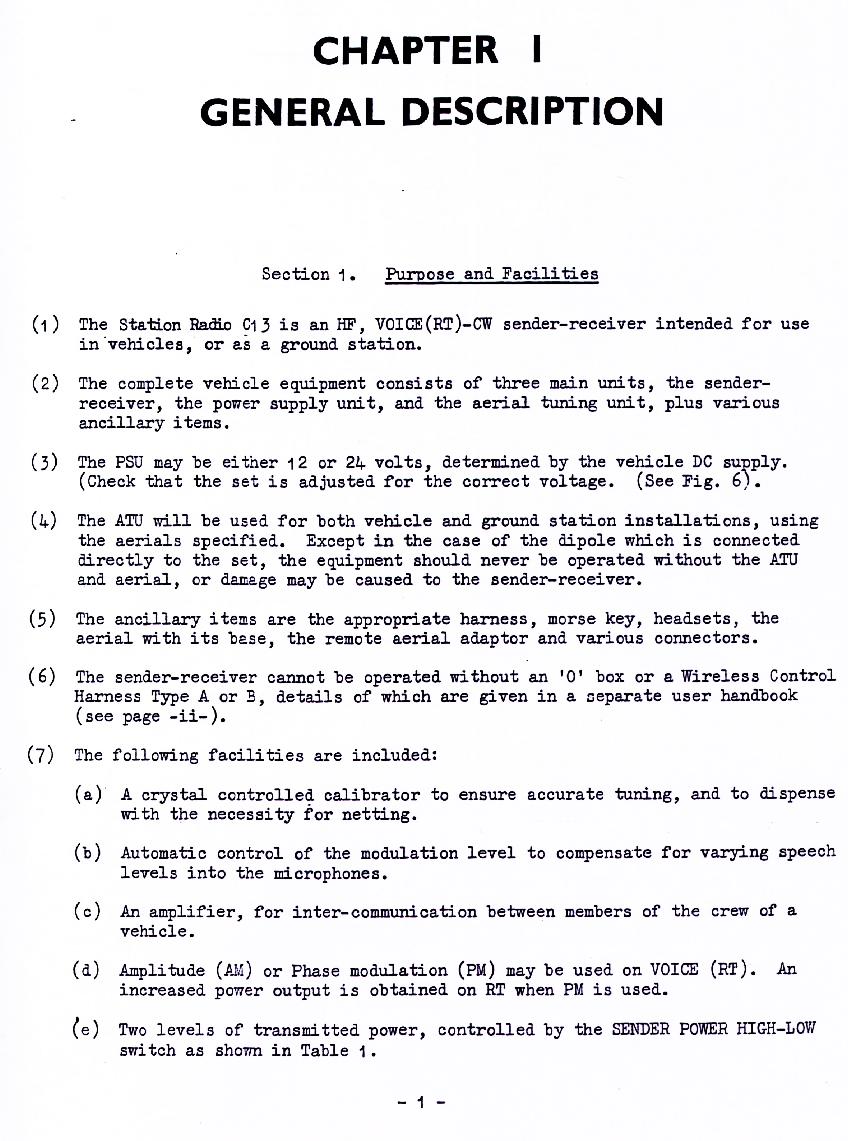
C13 military wireless set.
Larkspur
keywords: C13 wireless set, station radio, military radio, Larkspur, manual and schematics here
author: Ralph Klimek 2005
copyright: my notes and observations and designs are free to all. HOWEVER, the manual and manual images are still copyright.
I had acquired one as a boy. It was a delight to behold. The insides
appeared miraculous. I had never encountered a truly complex
electronic object before. Although I had no manual, I reverse engineered
sufficient of it to biuld a control unit and power supply.
This device was to
become the operational core of my ham radio setup, it become a stable
source of carrier, a variable IF, and a source of frequency
callibration as time when my hobby were financed through a bit of
pocket money. It taught me enough practical electronics to get me a job and see me through life.
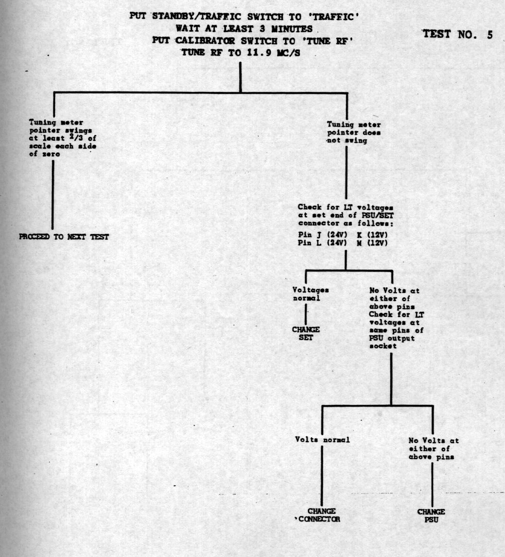
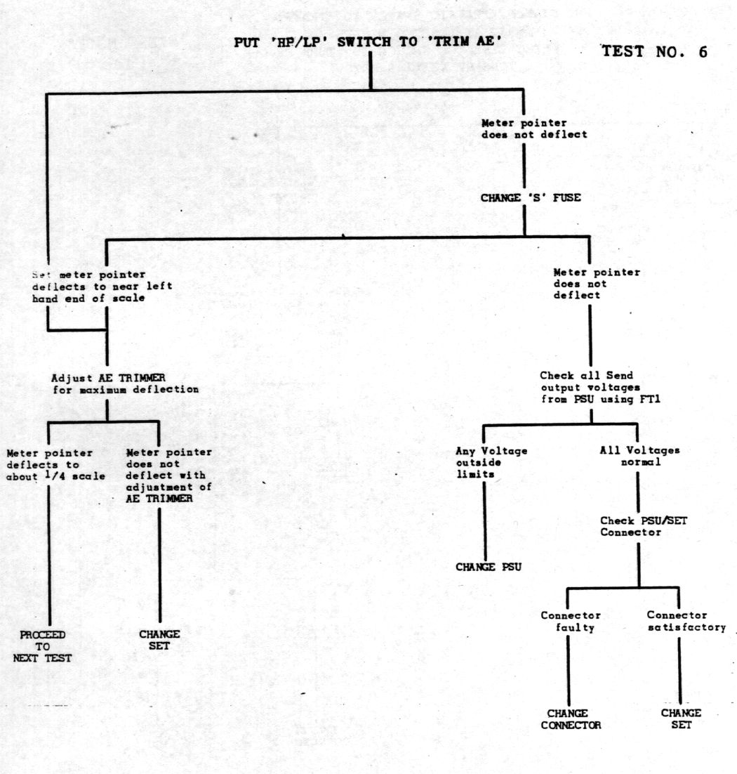
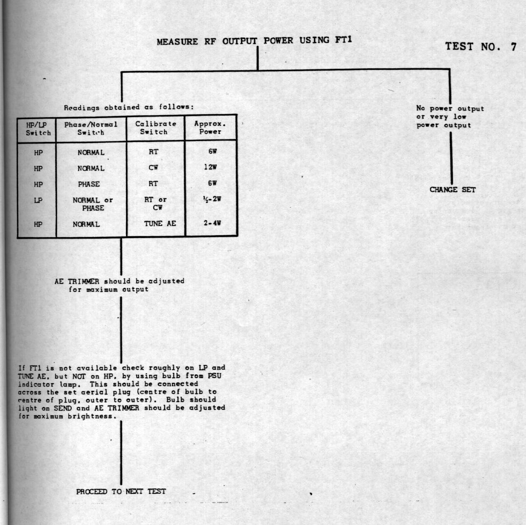
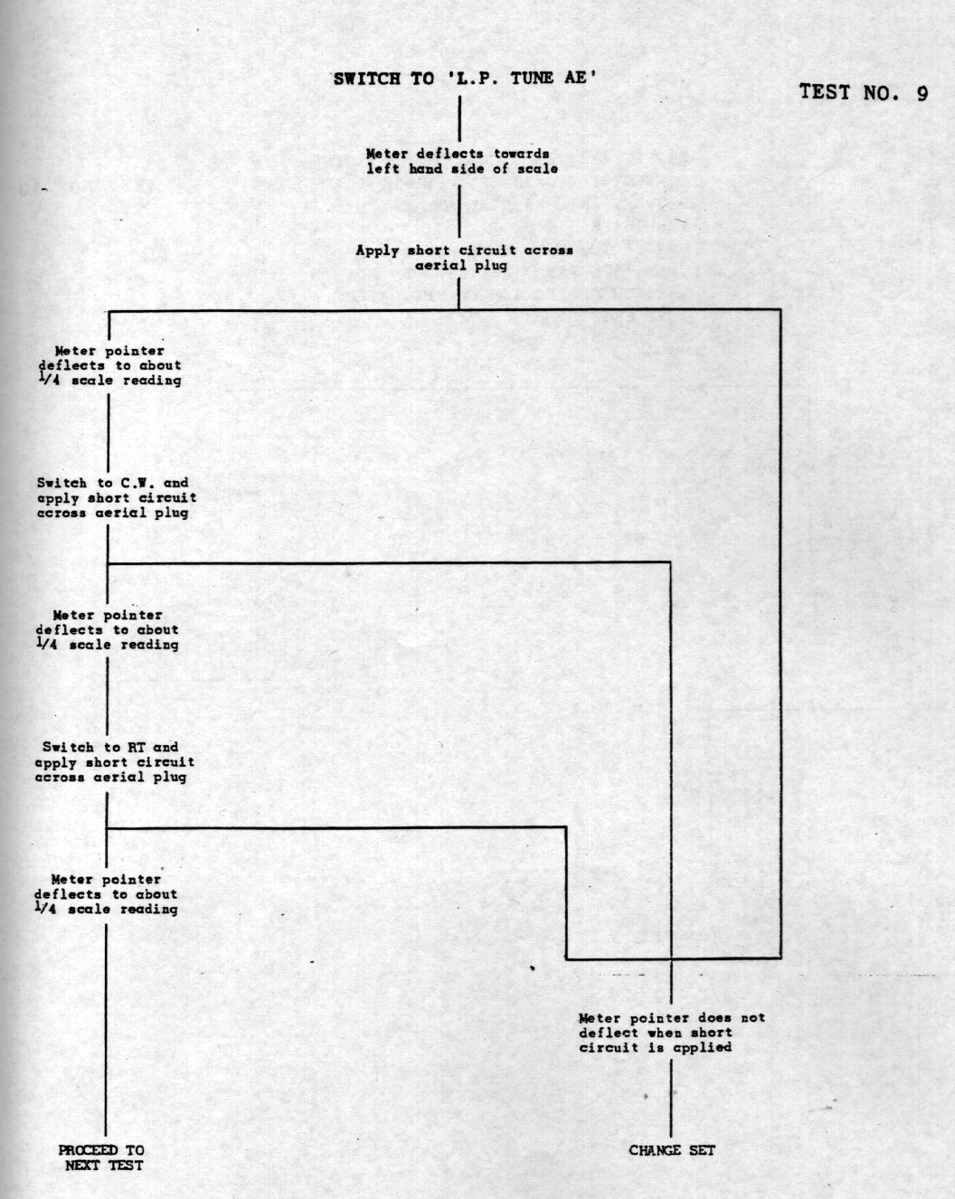
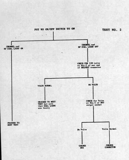
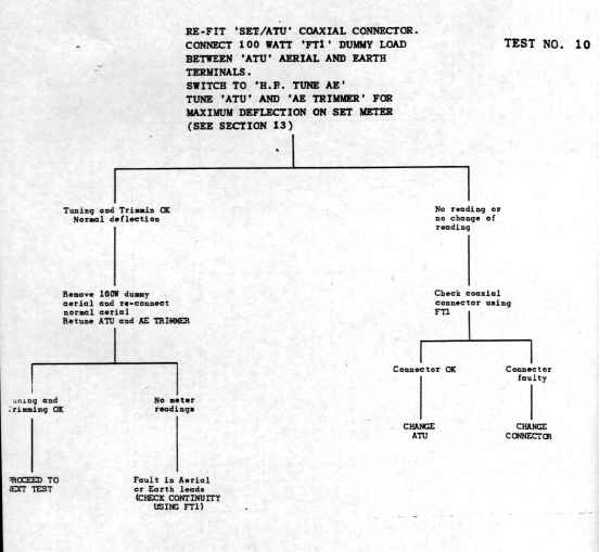
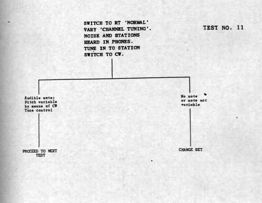
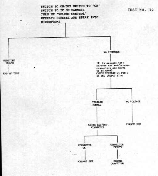
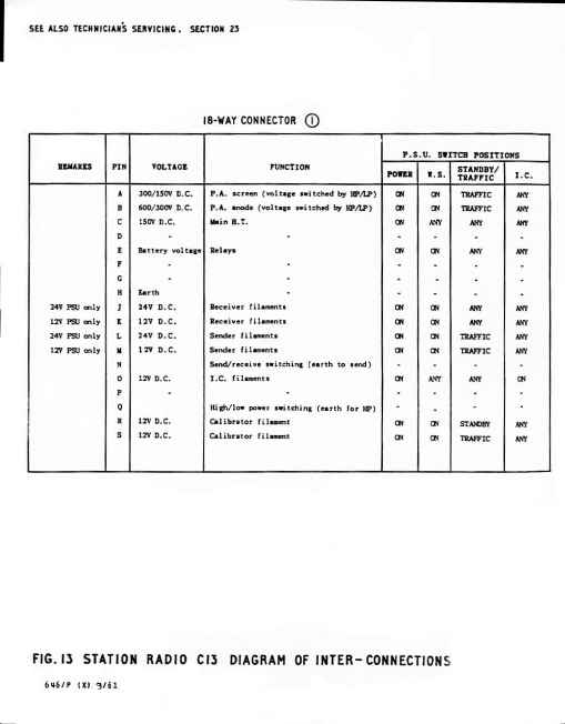
I have searched for 30 years for a manual and schematic for this
amazing piece of military history and I finally found one. It is
scanned in its entirety and the images manually cleaned up.
These images are low resolution thumbnails. Click on each to get
the high resolution page or download the entire manual tarball.
Given
the extraordinary biuld quality of this set, if you are fortuneate
enough to aquire one, it will probably just work without further ado.
If
you are using the original vibratory supply, your 24VDC source must be
clean because this voltage source is used for some low power
requirement biasing voltages internally. A 24V vehicle
battery supply was assumed. Complete sets with all external
harness and the elusive external ATU are extremely rare. The ATUs
were removed by surplus dealers for their Silver (Ag) content and very
few ATUs made it into the hands of hams. It is not difficult to
replicate the basic functions of the external harness. You will require
an external microphone amplifier should you wish to put it on air.
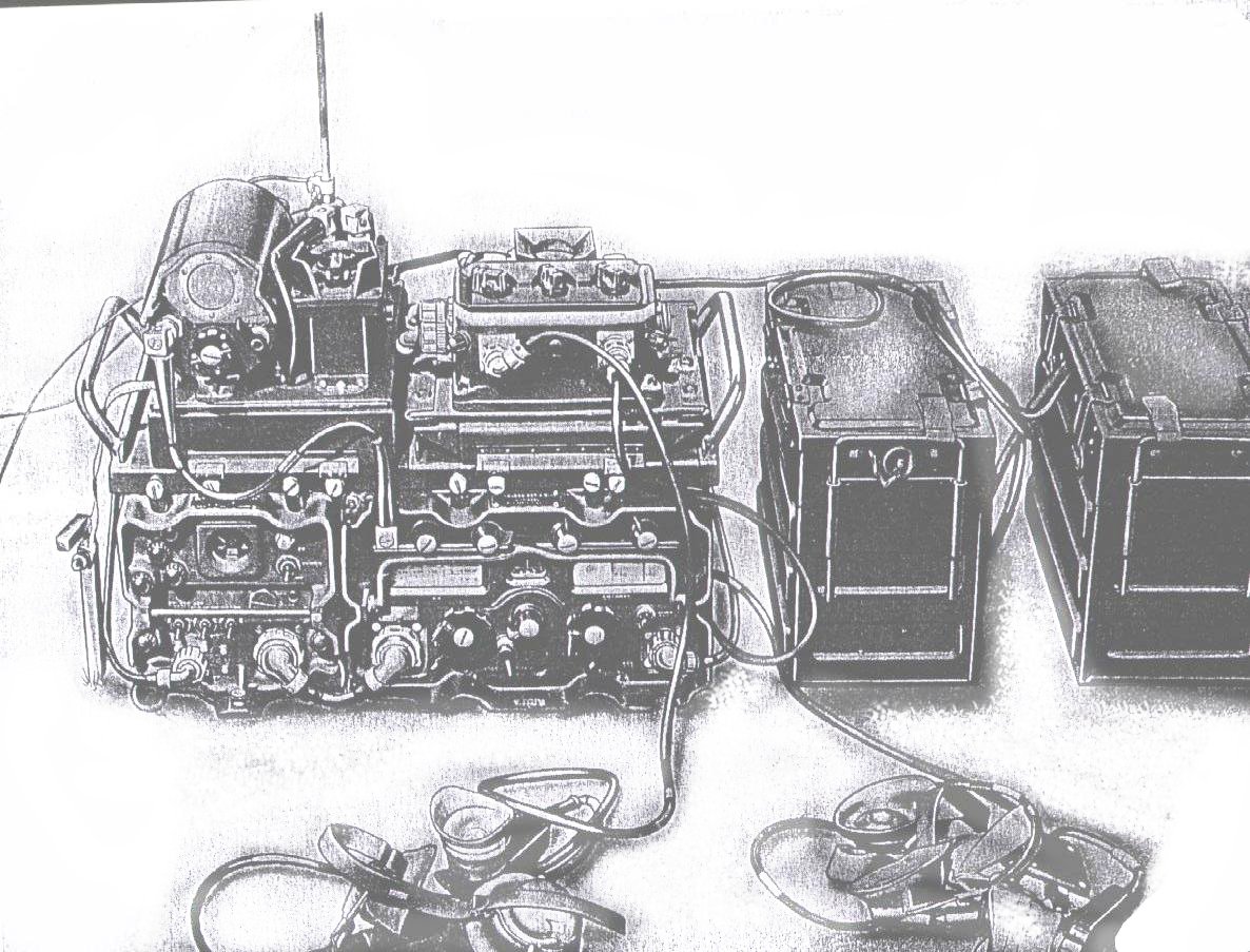
Here it is !

| 
| 
| 
|
| | | there were user servicable parts inside! |
| 
| 
| 
|
| | | |
|  | 
| 
|
| | | |
 | |  | blank |
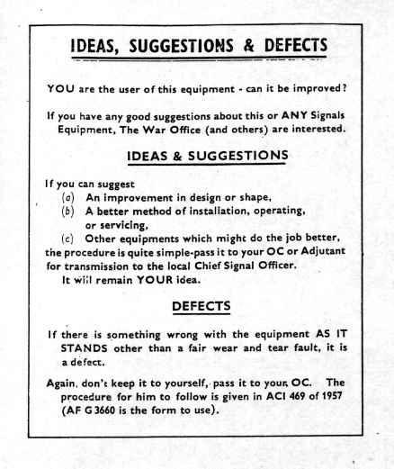
| | this is gorgeous! Do you think anybody ever did ? What would your adjutant have done? | |
This
link takes you to the next page of schematics
some
internal images taken during a recent dust off, Jan 2010. I have not
opened the case in twenty years. It still has the smell that is unique
to the larkspur equipment... sweet rubbery goodness ! Shown
here is the reciever module swung out on its mainenance hinges. I did
not have time to disconnect the front panel hardware to permit the
transmitter half to swing out. Items of interest to look out for are
the back of the ledex rotary relay on the sender module and some of the
film strip dial and variable capacitor clockwork. The transmitter
bottle is mounted in a teflon socket and sits infront of a RF sheild
that some very clever person saw to that it was finely polished and
doubled as a thermal reflector, helping to passively dissipate the RF
final bottles' heat against the aluminum case. This radio was
passively cooled unlike other larkspurs ( like the C42, C45 , C11 et
al) that had a small internal fan. Purists will note that the
internal dessicator is missing. This vanished about 35 years ago. When
I bought it ( I was only 16 at the time ) I did not recognise its
function. Maybe it was a demollision charge! , or so I thought, so I
quietly disposed of it. I am still amazed at the very high
component packing density.
home page

this page was modified on Thu Apr 17 19:19:47 EST 2008 to improve useability and download speed
added email sig Tue Jan 5 18:29:07 EST 2010 Mon Feb 1 18:23:52 EST 2010 added pictures of C13 internals