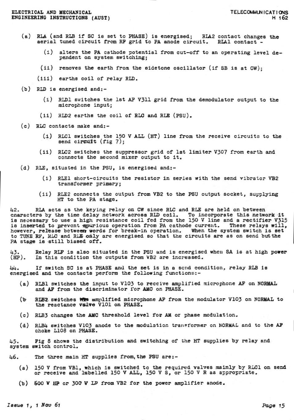
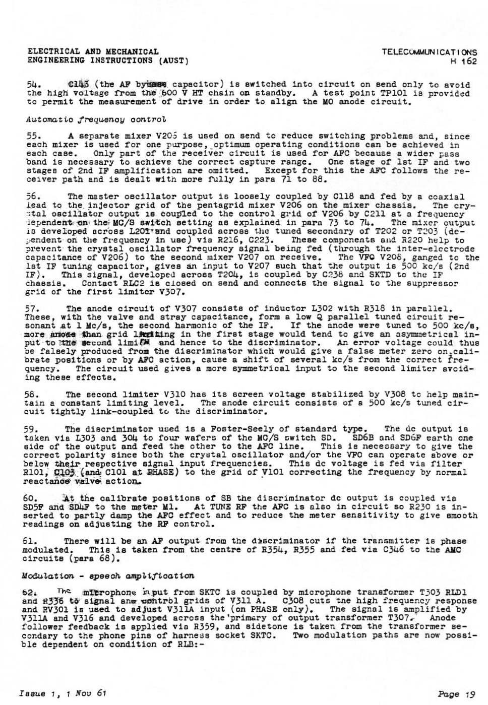
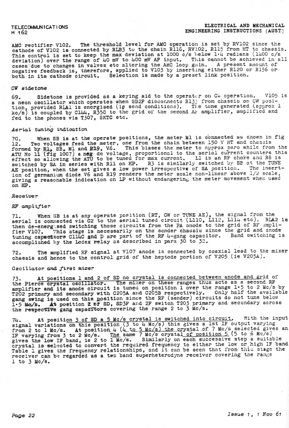
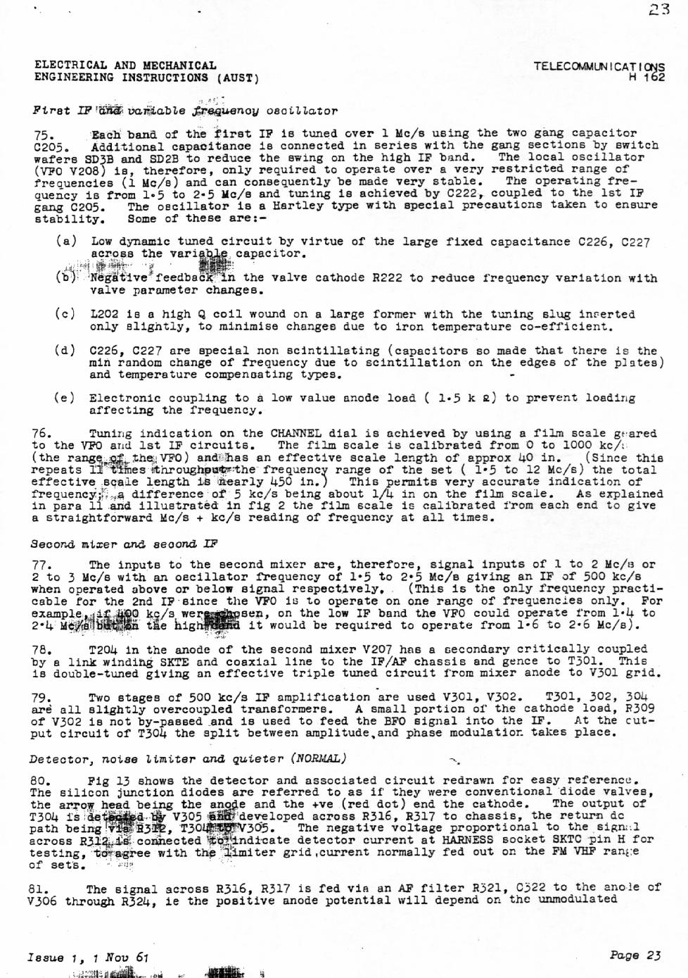
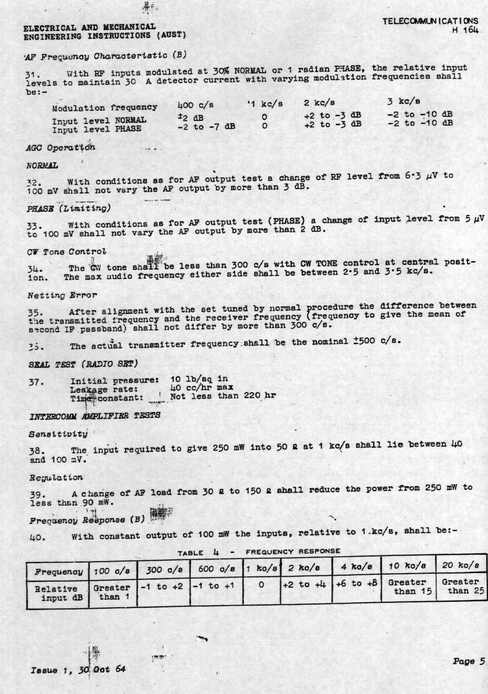
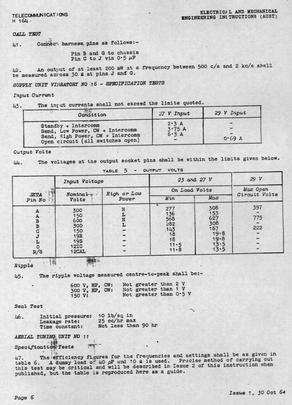
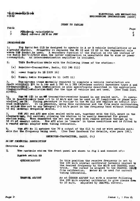
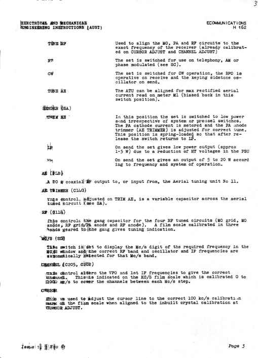
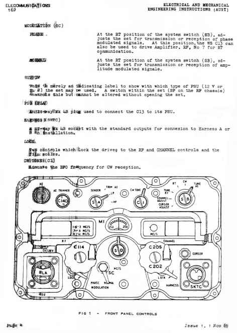
this page shows the schematics for the station radio
wireless set C13
individual images are links to their high resolution images
 |  |  |  |
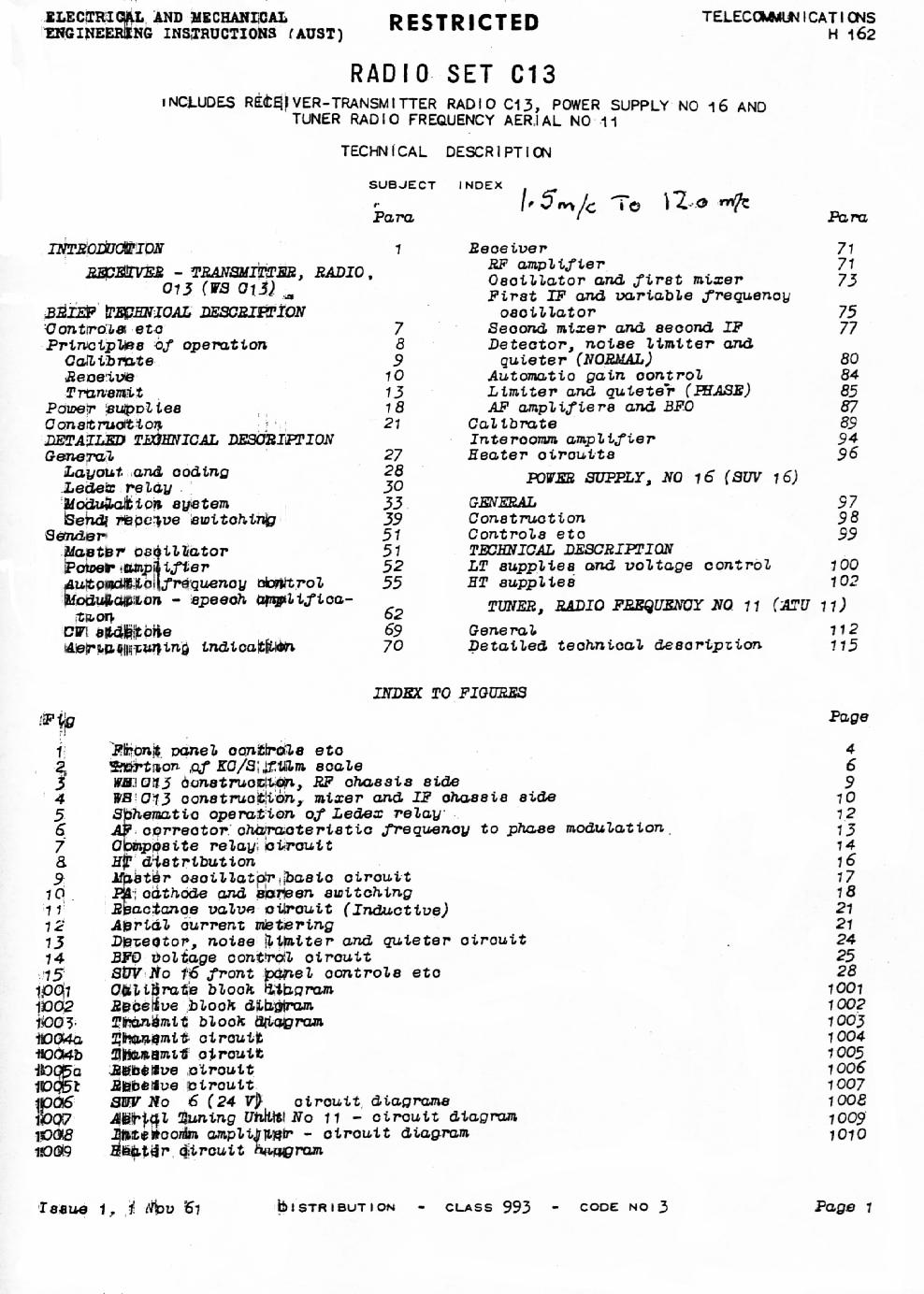
| table of contents | | | |
 |  |  |  |
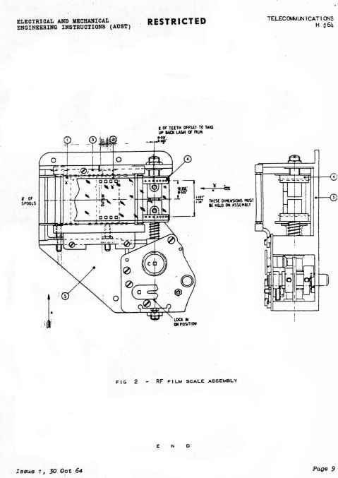
| film strip cam | | |
it really does fold out like this, the real image is amazing. It is
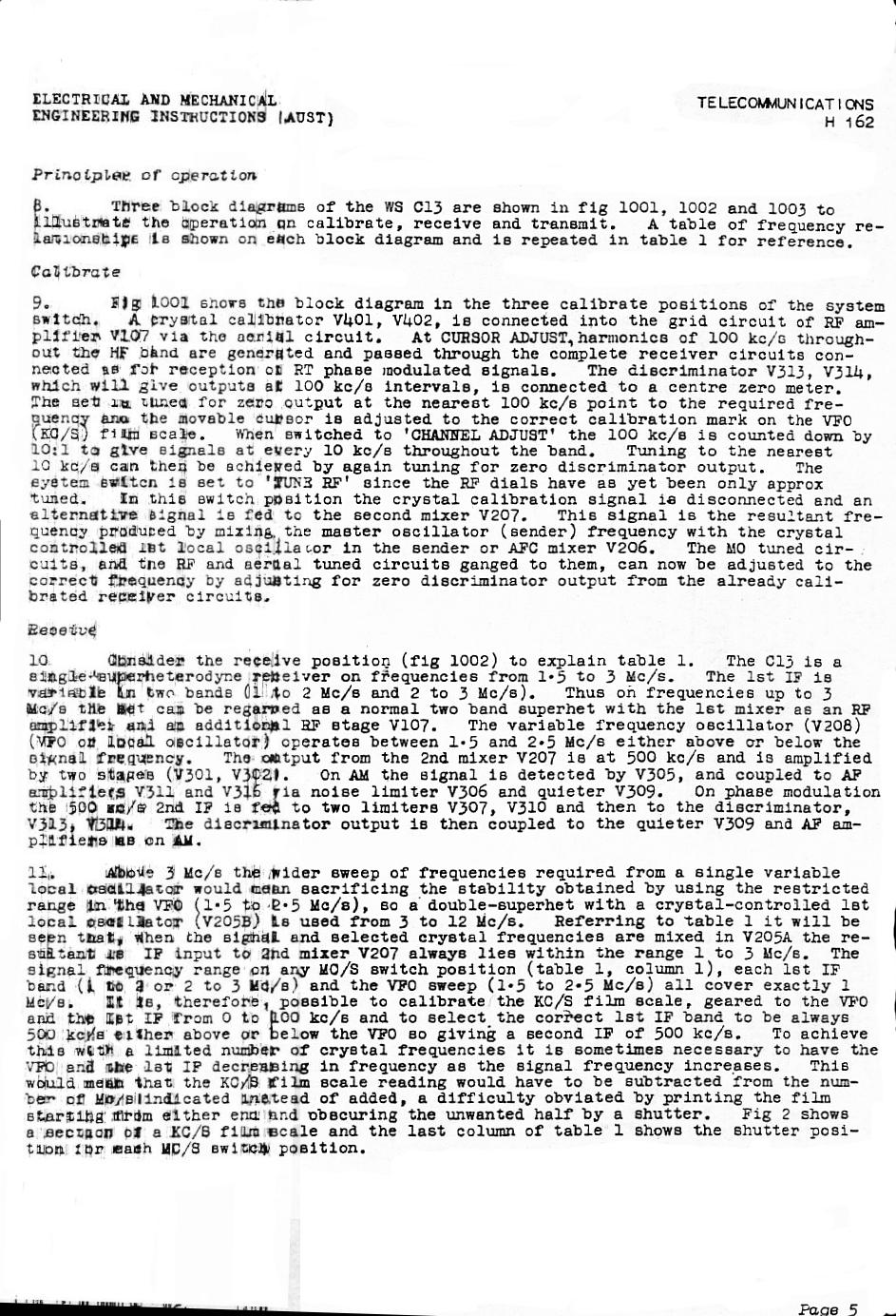
truly the roll royce of radios
 |  | 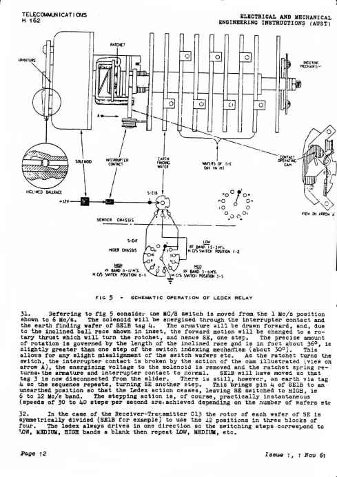 |
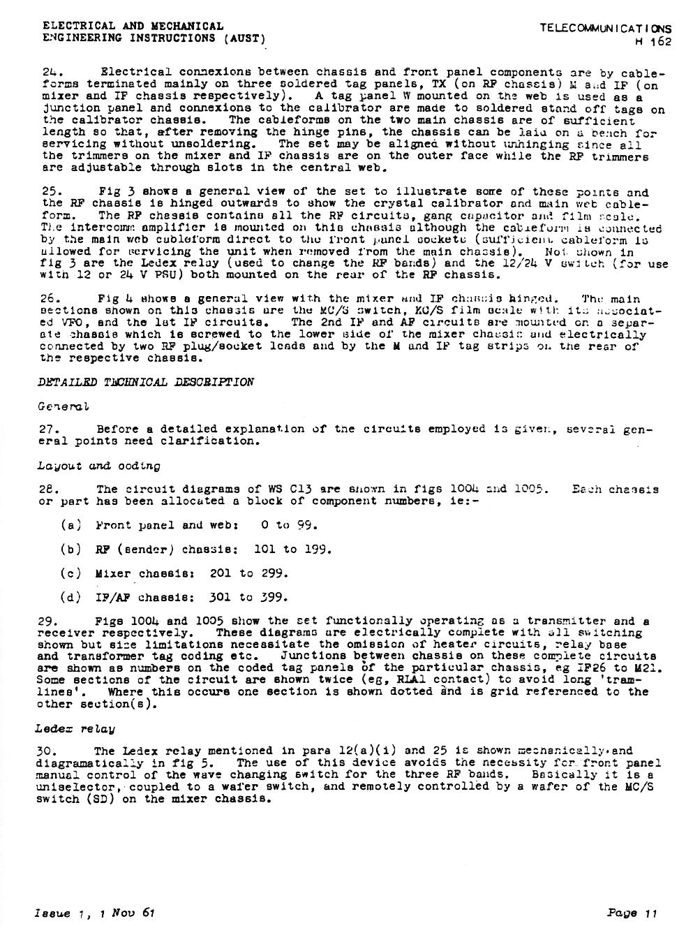
| | ledex rotary relay |
 |  |  |
| summary of relays | |

|  |  |
| | |
 |  | 
|
| | the C13 external PSU |
 |  |  |
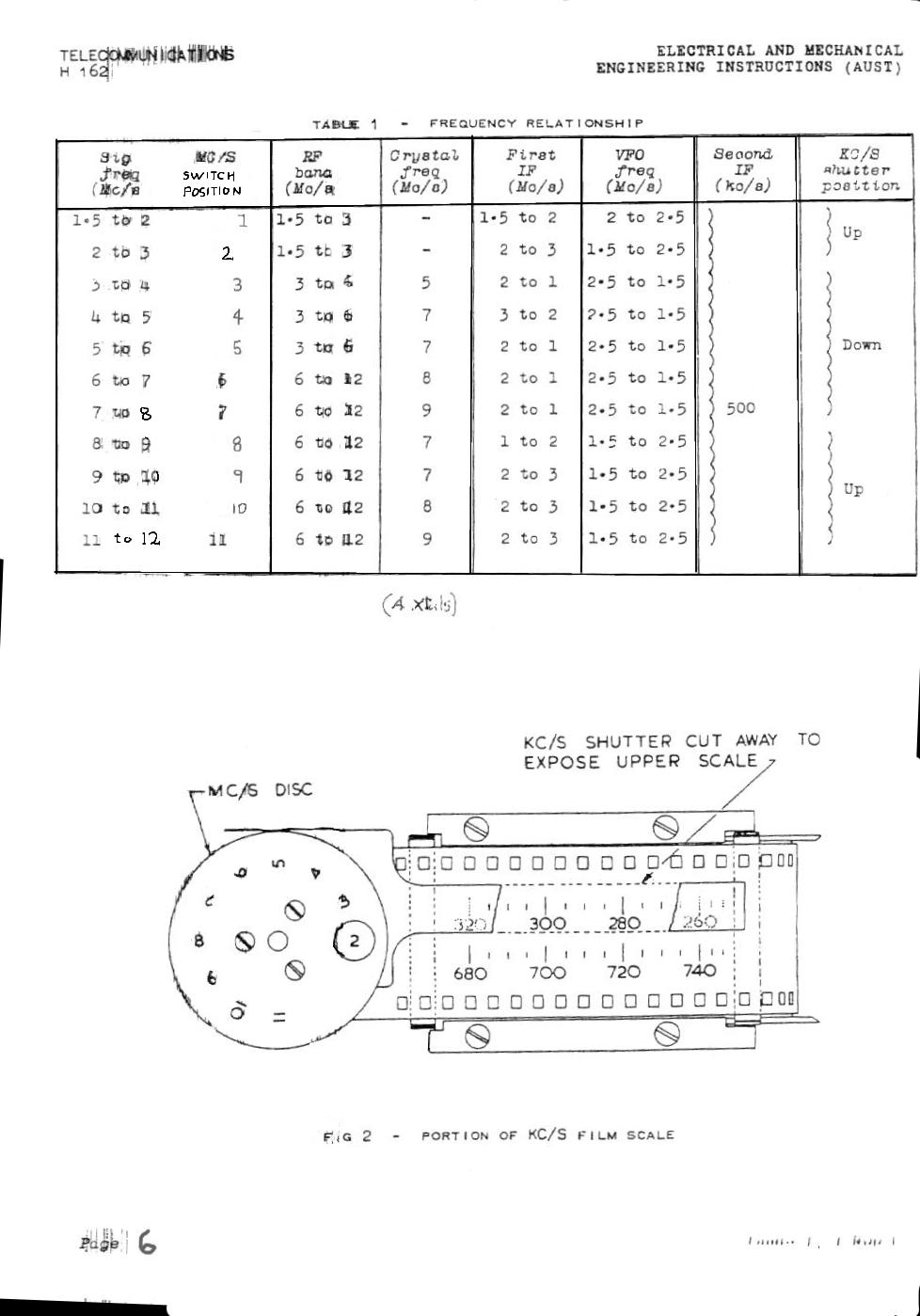
| calibration system | receiver block diagram |
 | blank | blank |
| transmitter block diagram | | |
 |  |
| |
 |  |
| |
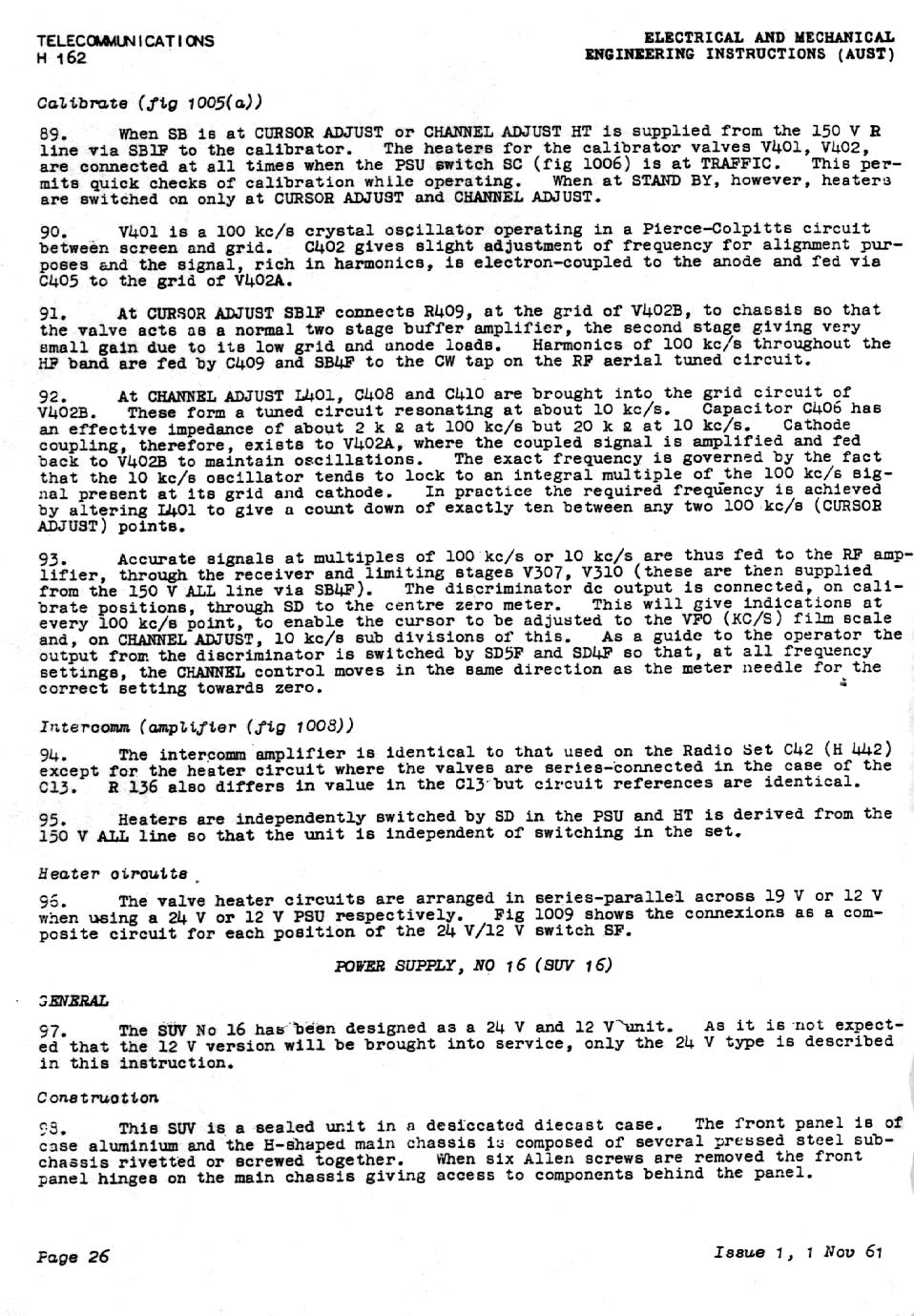
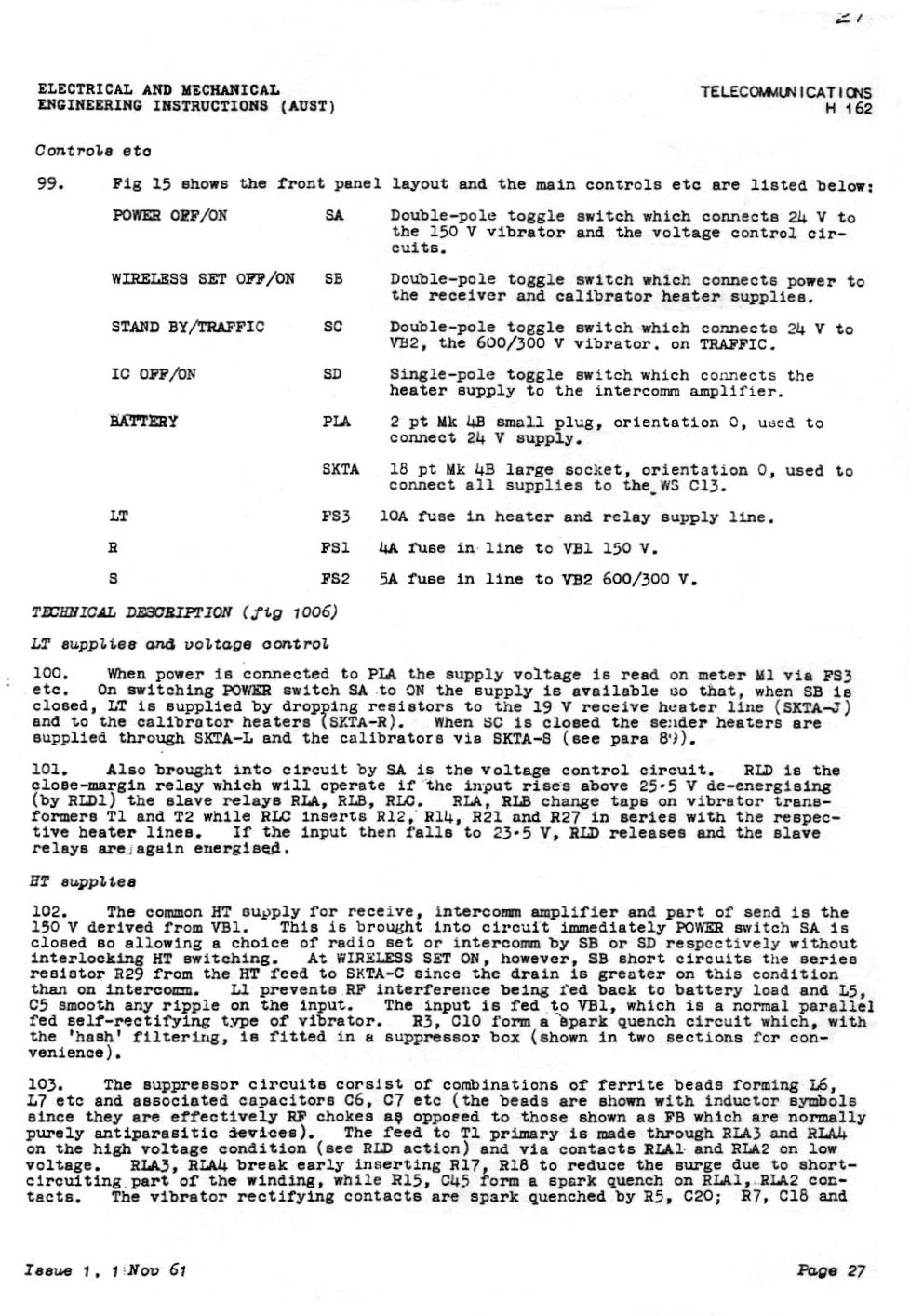
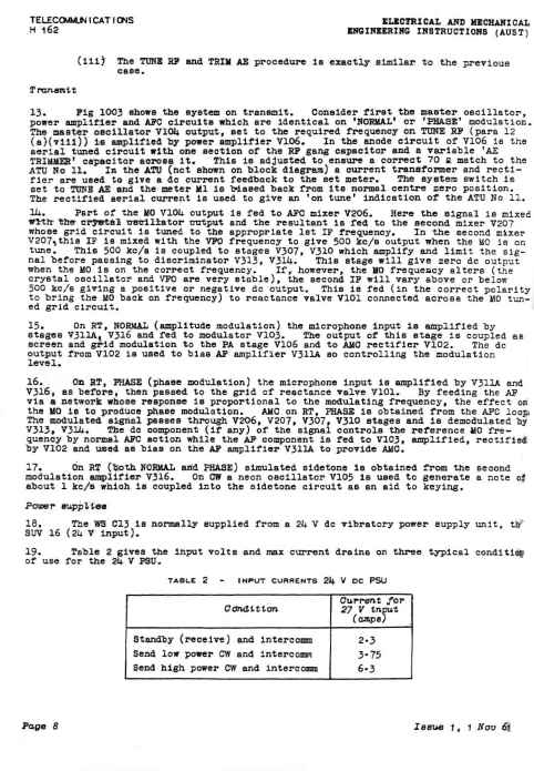
 | The psu was the only dissapointing part of the system. It needed 24V at
a gazillion amps. The vibratory supply gave poor regulation. I should
have fed mine with 24V AC and replaced the vibrator with diodes but I didnt have a schematic and reverse engineering it was
impossible due to its ultra compact construction. Instead I
biult
my own DC regulated supply which allowed the C13 to truly shine.
My reverse engineering was accomplished by monitoring the power harness
voltages under various operational conditions and designing something
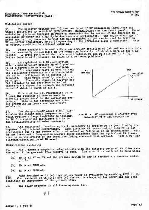
that behaved the same ! The older C42/45 used a solid state inverter. |
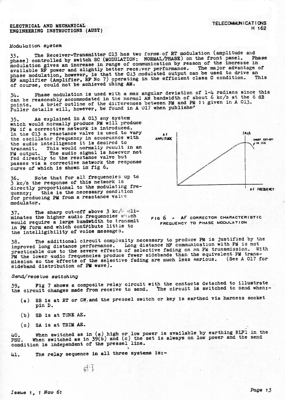
| External PSU | |
 |  |  |
| the "intercomm" amplifier chassis | valve heater chain | |
 |  |  |
| | |
 |  |  |
| | film sproket mechanism |
 |  | blank |
| film sprocket mechanism detailed | |
using tables to improve layout, low res thumbs to improve display speed
Tue May 6 17:42:57 EST 2008, fix some errors Tue Jan 5 18:29:07 EST 2010