a must build for QRP


shock horror...surface mounted detectors !
| A
return loss bridge is the absolutely simplest method of antenna
matching. When developed in the full sense, it is possible to do
precision impedance measurements. In the simplest use case it
becomes trivial to match an arbitary antenna load with an ATU and
have confidence in the match achieved. An ATU can be pretuned
without tuning up on air with just a signal generator and sensitive
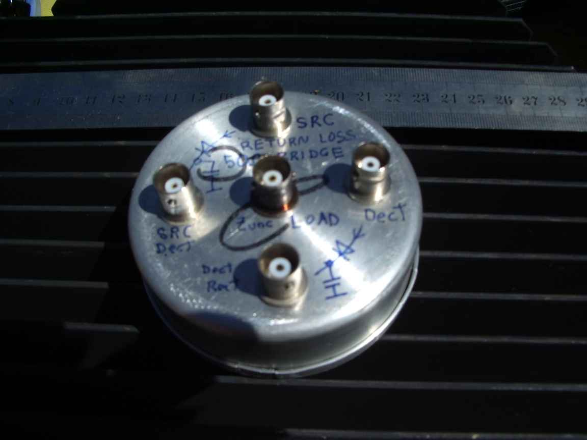
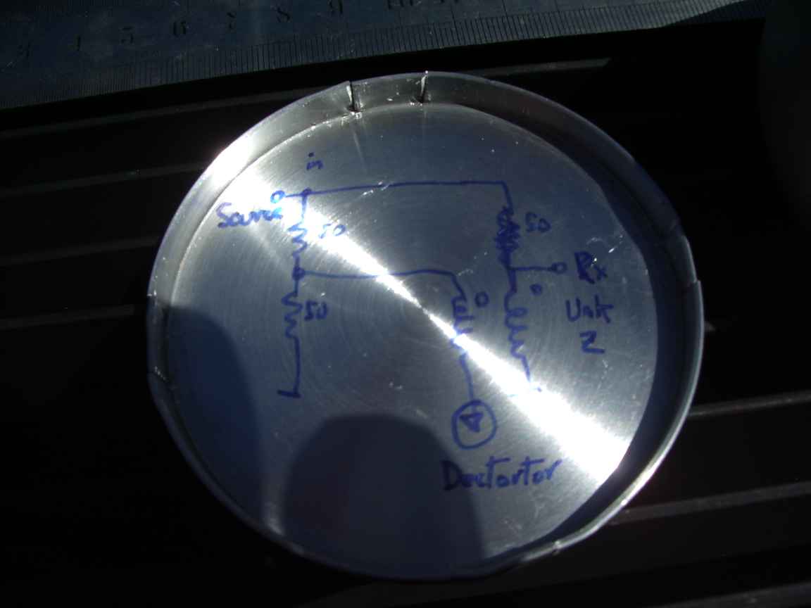
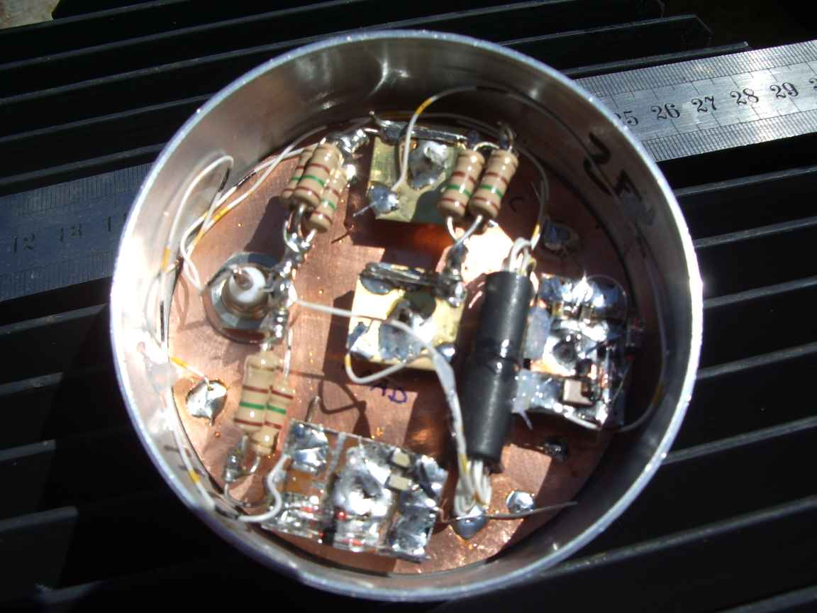
detector like a HP-411A rf millivoltmeter or just a radio reciever, provided it is to 50ohms or other. Other "normalised" impedances need to be specifically designed for. Mine is for 50 ohms....what other kind of ohms are there? 75 ohm impedance cable actually has LOWER transfer loss than 50 ohms. Why ? Dilectric loss scales as the first power of voltage. Ohmic loss scales as the second power of current. Why does the radio comms world settle for 50 ohms? It is a long story, not to be told here. I have used three paralled 1Watt 150 ohm resistors. This permits tuning up with QRP level transmitter levels without risk of burning the bridge out. I have also provisioned diode voltage detectors for Source and Load terminals. USAGE for simple tuning consists of adjusting your ATU controls to achieve a bridge null. Thats it, nothing more , nothing less. A null means 50+j0 ohms. The bridge detector coil serves the purpose of converting the balance bridge signal to an unbalanced ground reference signal for the detector. I have used two binocular cores cemented together to get extended low frequency coverage. Five bifilar turns give usefull coverage down to about 2.5 Mhz. This is disappointing, I was aiming for usefull coverage below 1.8 Mhz. Next interation will have 3 binocular core in the transformer. Maybe my randomly chosen cores had lower permeability than expected. ( note to self, next time measure, measure, measure measure...) This iteration still provides usefull indications up to 54Mhz but bridge balance is uncertain up here. Something would have to be purpose biult for VHF coverage, this layout is not suitable for VHF. I found these cute circular spun aluminium cans in a dumpster at work. No idea what they had been intended for. |
| and Now ! |
| a simple return loss bridge for VHF-UHF and L-band microwaves |
| This
resistance loss bridge is a newer, yesterday's, next generation
design. This implementation features hand made low inductance
resistors, a double ferrite balun and the shortest lead lengths that I
can do. The 50 ohm resistors have been made by soldering together 4 of 200 ohm 0.5 watt surface mount resistors together to get a very nice 2W 50 blocky package. The decooupling sleeves are bog standard ferrite binocular cores. The coax cables are teflon 50 ohm precision coax. This stuff is marvellous because it is so easy to solder and being teflon will never melt, no matter how clumsy we are. This design is truly broadband, its accuracy is limited only by my lack of precision dummy loads that still look like 50 ohms above one gigahertz. Most do not. The length of the ferrite sleeve allows satisfactory usage down to 10Mhz and is still just plausibly accurate up to 2Ghz , according to my sweep generator, but again I do not trust my 50 ohm load at 2 Ghz. There are a few things that need to be understood about this design. It is basically a simple resistive Wheatstone bridge, made with UHF/microwave grade components. A external ferrite sleeve standard coaxial balun converts the balanced signal from the reference and unknown arms of the bridges to an unbalance ground referenced signal. The ferrite prevents RF currents from tranversing the outer braid of the balun. So what is the OTHER line for, the one that appears to short the reference arm to ground ? The balun part, still has an UKNOWN intrinsic admittance to ground in parallel with the LOAD terminal due to stray reactive currents along the length of the balun. This must necessarily disrupt a simple measurement. The other "useless" line has pretty much the same geometry as the ACTUAL balan , so that the admittance to ground mimics the UKNOWN intrinsic admittance to ground of the balun. This now automatically rebalances the wheatstone bridge ! without even needing to know what the stray balun to ground admittance actually is . So why the binocular cores ? These cores will never behave like a transformer E-I core because of the instrinsic core loss of ferrite at these frequencies, so they behave as if they were two completely independant ferrite sleeves. I use these cores to preserve symmetry of the geometry as far as humanly possible. The only real diffucluty here was with the 50Ohm type N connector, it really is not compatible with surface mount pcb construction. It has an aluminium offset plate to permit easy pcb mounting, but this necessarily adds mystery uncontrolled impedance in series with the test port which must compromise accuracy at 2Ghz. I am much taken with this design, the resistors can collectively dissipate about 3 Watts so it permit antenna tuneups with real transmitters in low power mode without fear of burning out the bridge. This design is highly reproducible and does not use any exotic components. Try and obtain a silver plated type N connector for the test port. |
 created page Fri Dec 5 18:17:15 EST 2014 added the UHF rlb Mon Mar 21 17:53:43 EST 2016 created page Fri Dec 5 18:17:15 EST 2014 added the UHF rlb Mon Mar 21 17:53:43 EST 2016 |