Here are my hand drawn reversing notes. good luck. They are about 85
percent complete. I have not been able to figure out how it decided to
use single or double conversion. The switch bank wafers are allmost
innaccessible and I cannot decode them. This switching is determined by
a switchbank at the rear of the chassis underneath the 2nd if module.
The switch bank is driven by a rack and pinion drive from the main
bandswitch turret. There is enough information here to debug most
A618 faults.
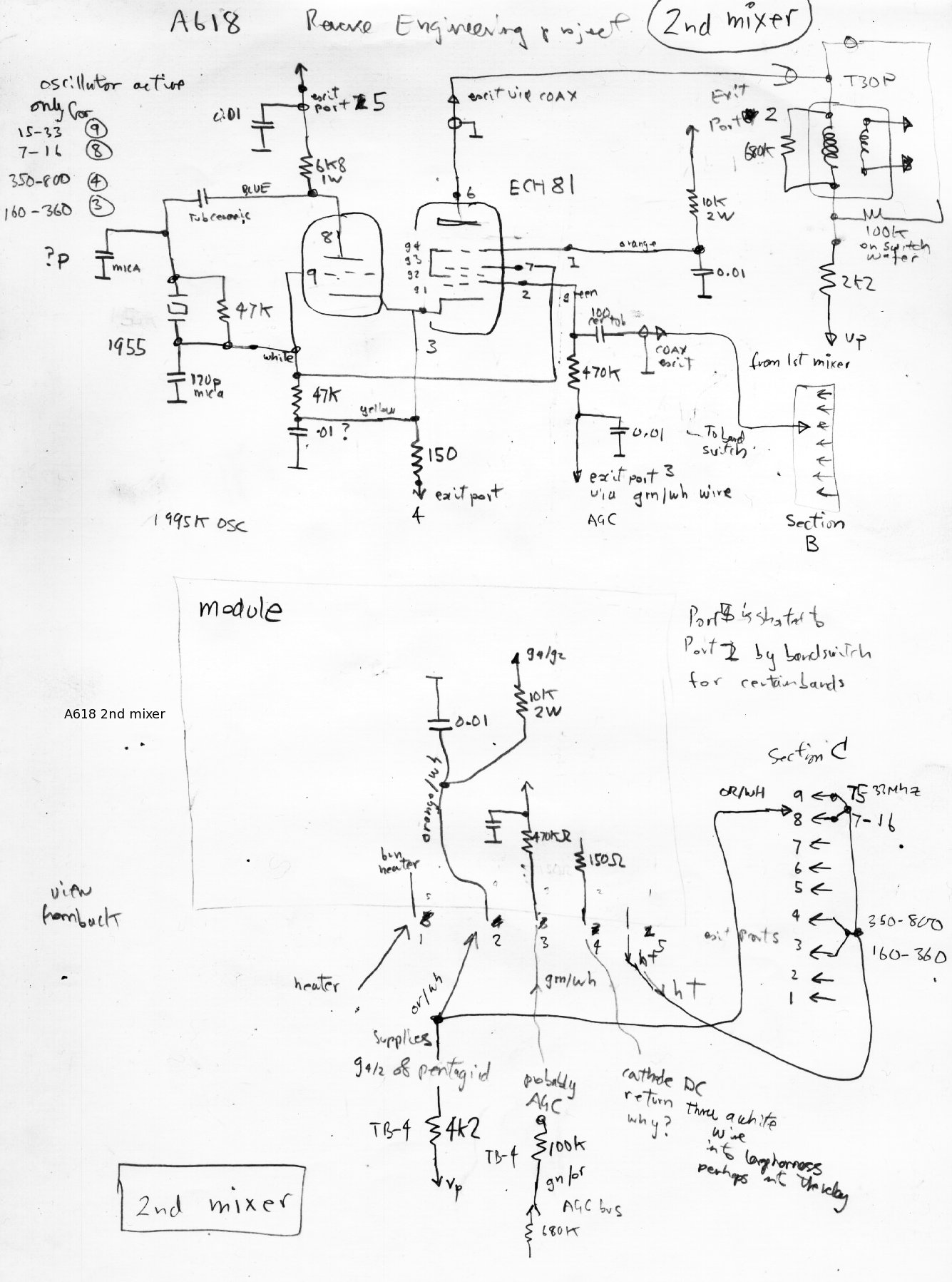
second mixer module at rear of chassis using ECH81 or CV2128 with 1995khz crystal osc
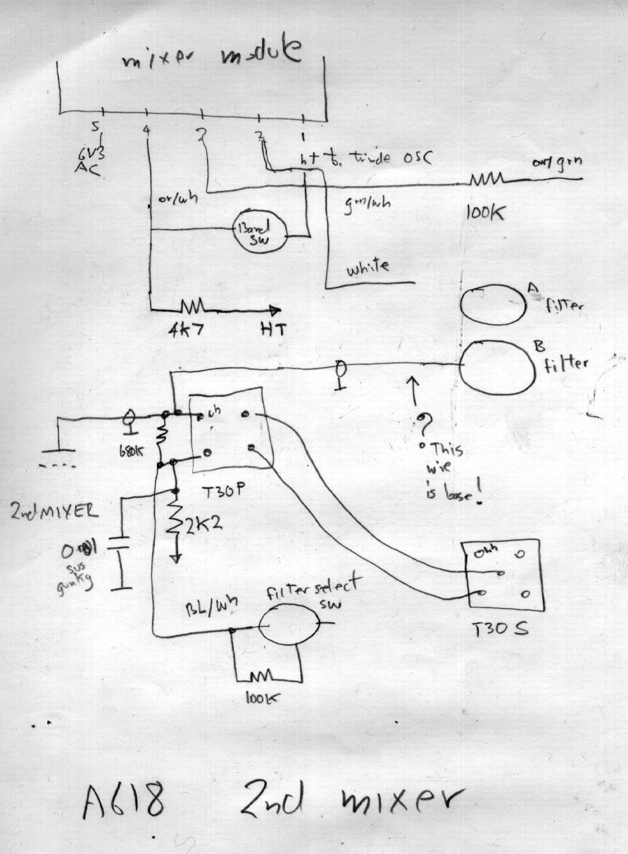
part of second mixer, under chassis wiring, mixer and first if transformer
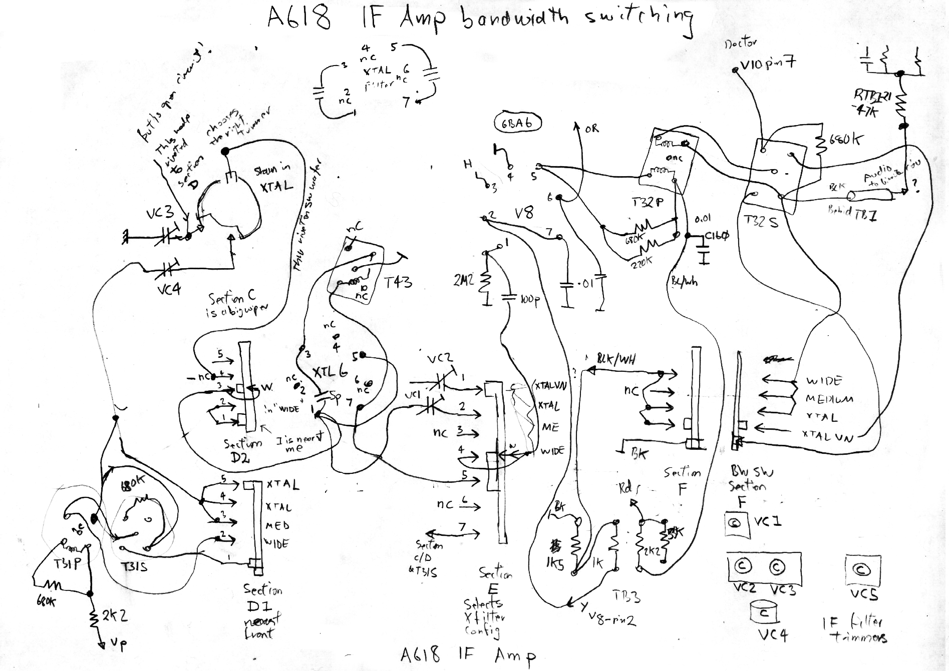
main if amp bandwidth selection wafers
This bit I dont understand. The switch bank is driven by rack and
pinions from the front panel if bandwidth control. There are 2 stages
of transformer coil determined bandwidth, one position inserting the
quartz resonator in narrow mode and in "very narrow mode" a 800Hz
parallel resonant LC filter is inserted in the audio path.
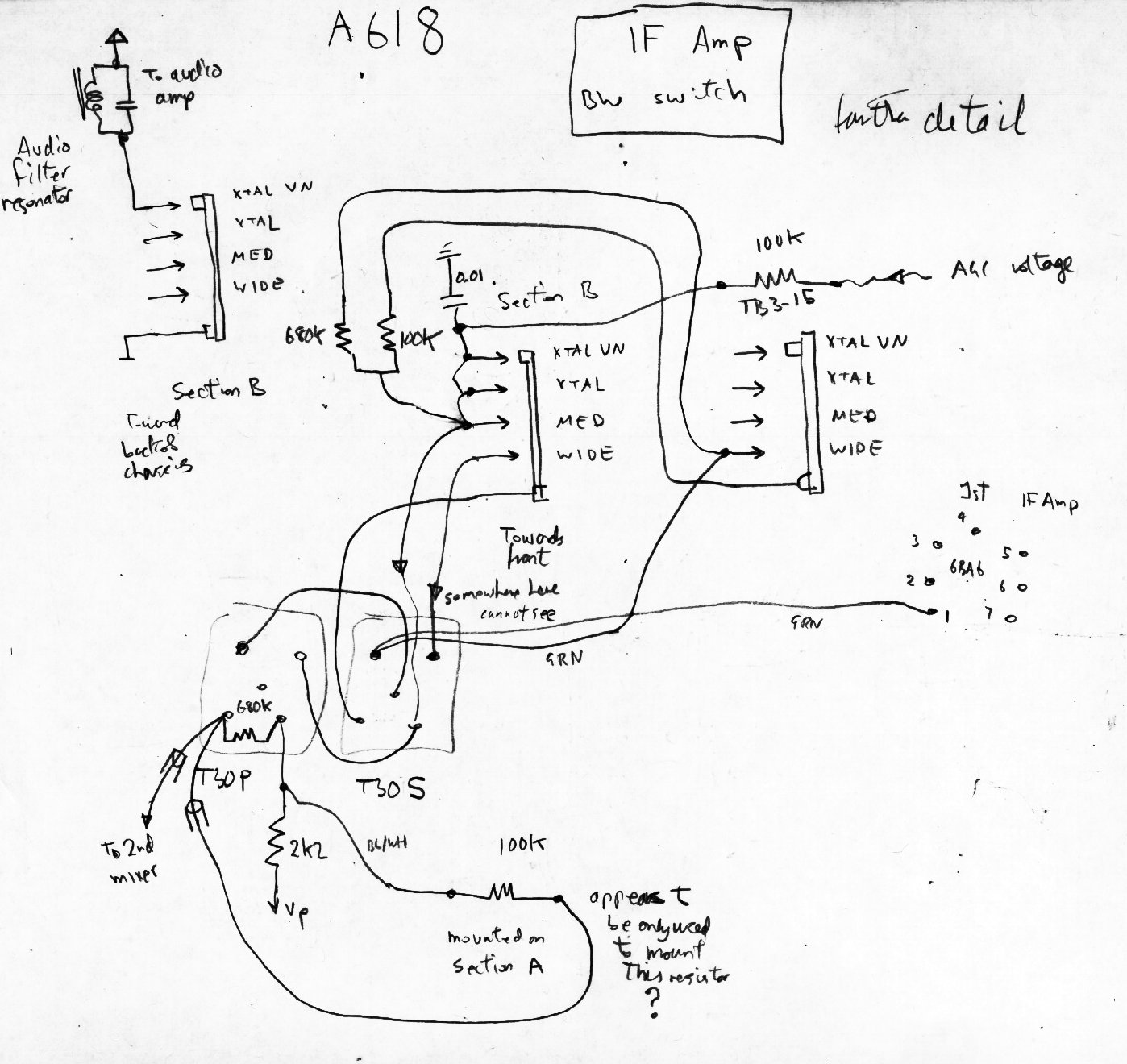
bandwidth selection wafers, very narrow mode LC audio filter is inserted here
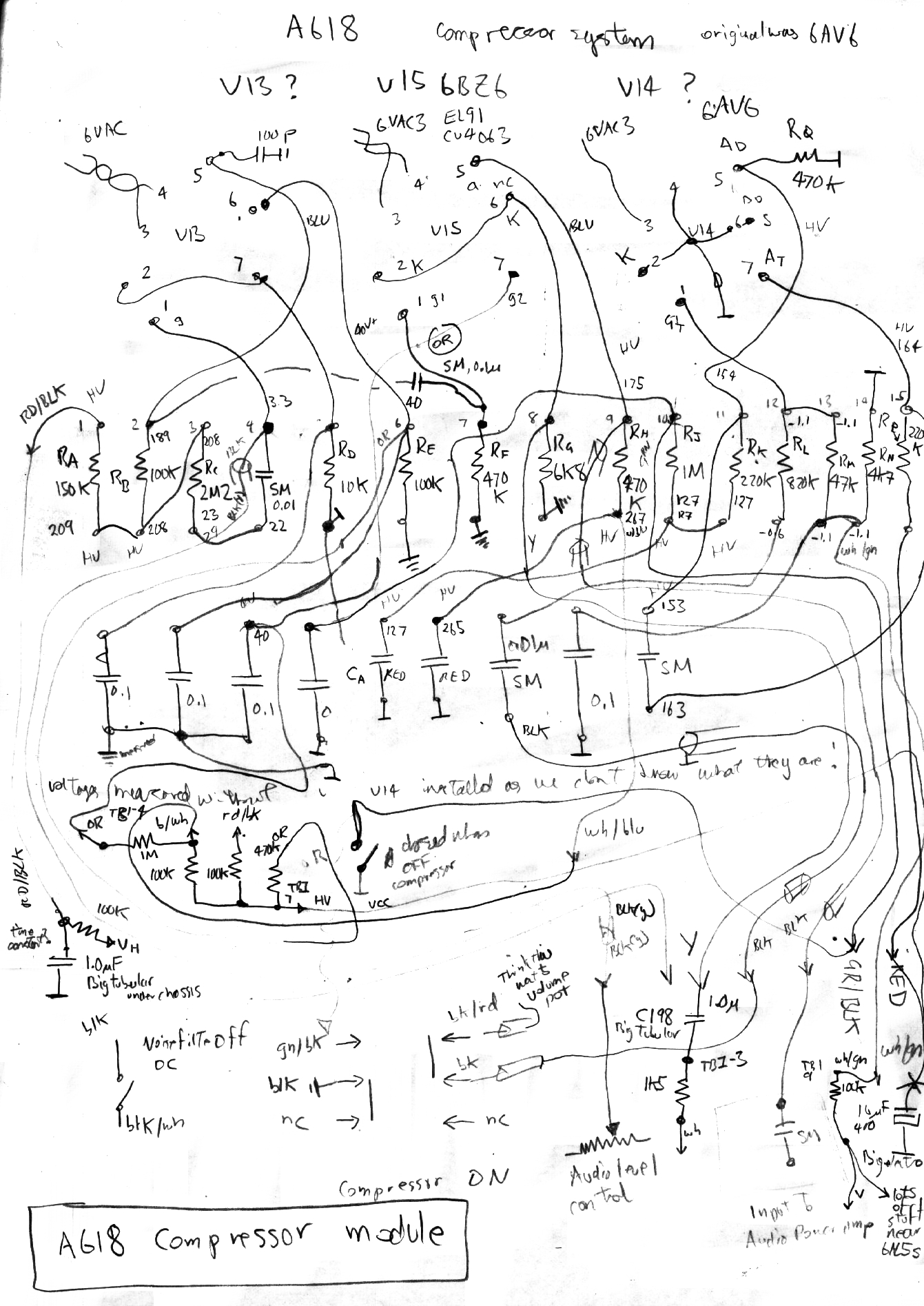
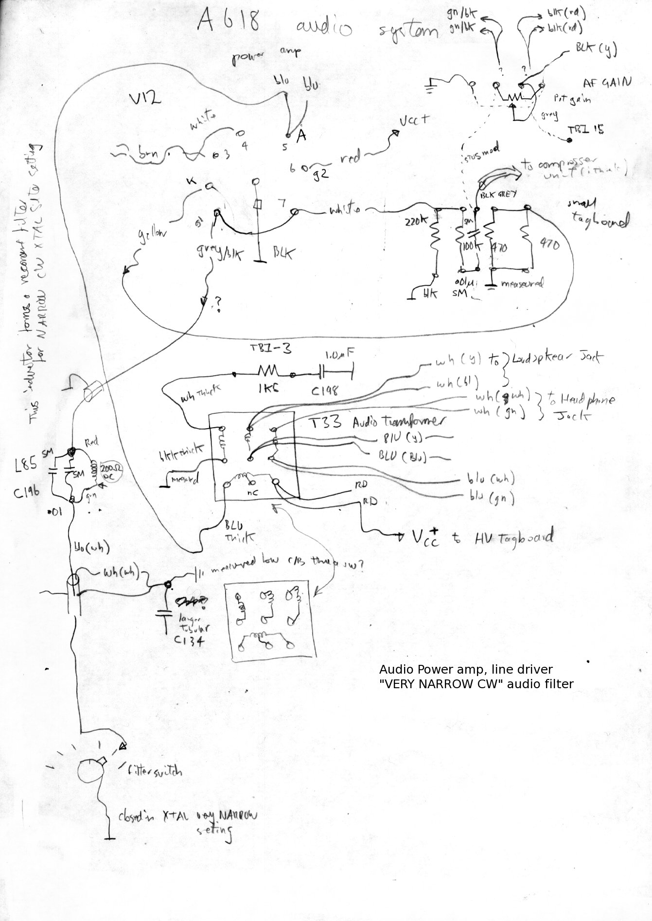
post dectector audio amplifier and compressor. see the inferred schematic below.
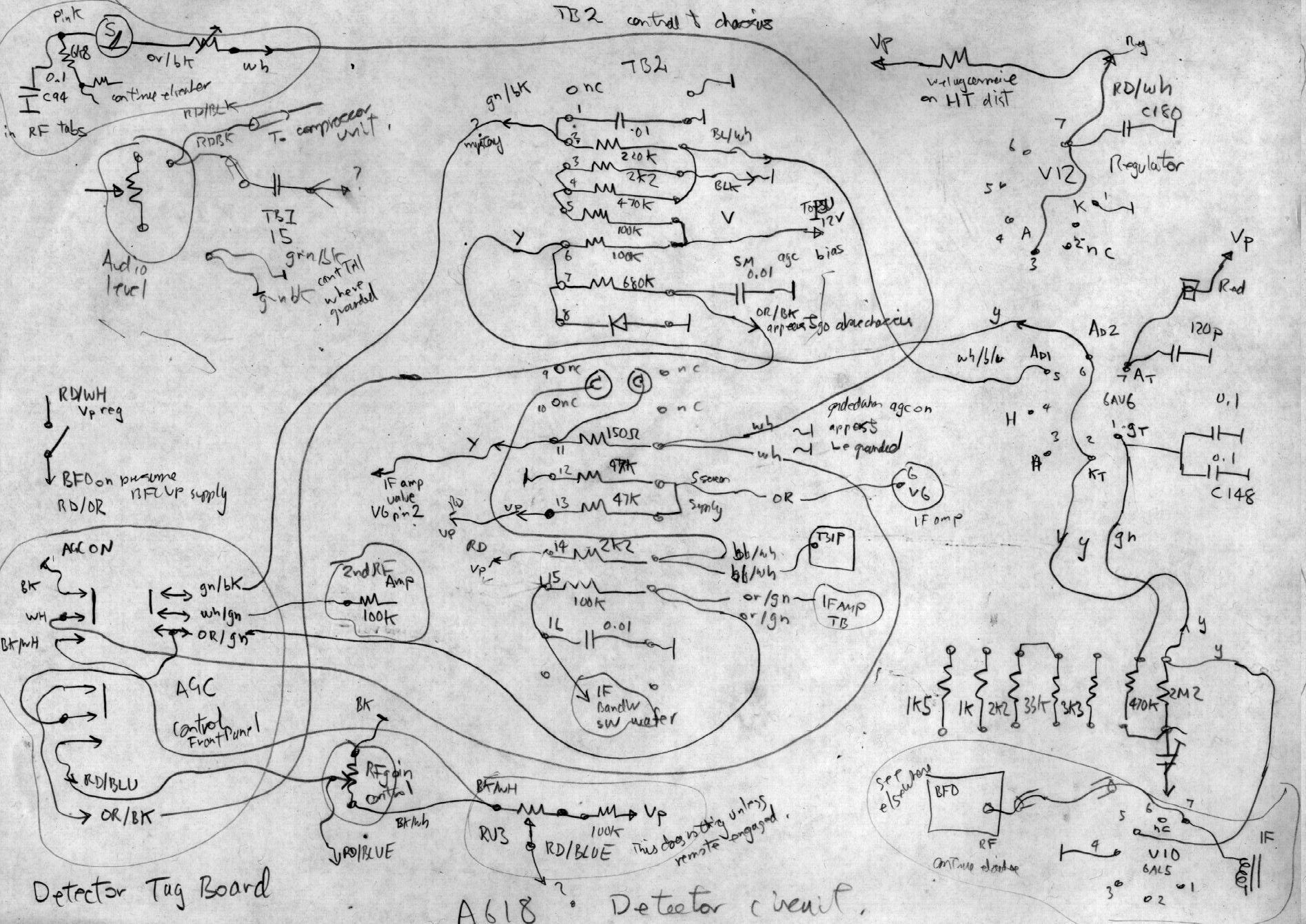
detector, agc, delayed agc, noise limiter, manual IF gain control, S meter drive
audio power amp, filter CW in very narrow mode
under chassis central tag board, detector,agc,agc control switch
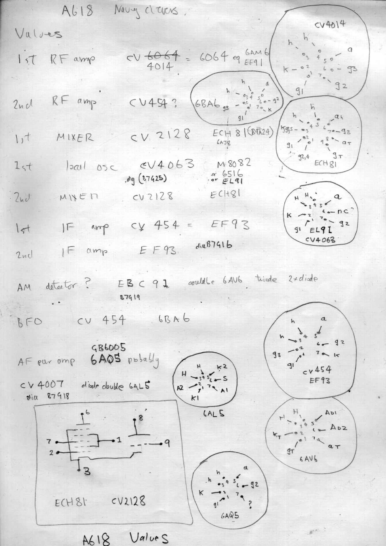
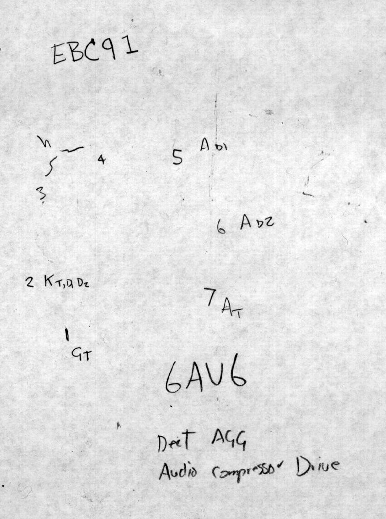
schedule of valves used in the A618 and base diagrams
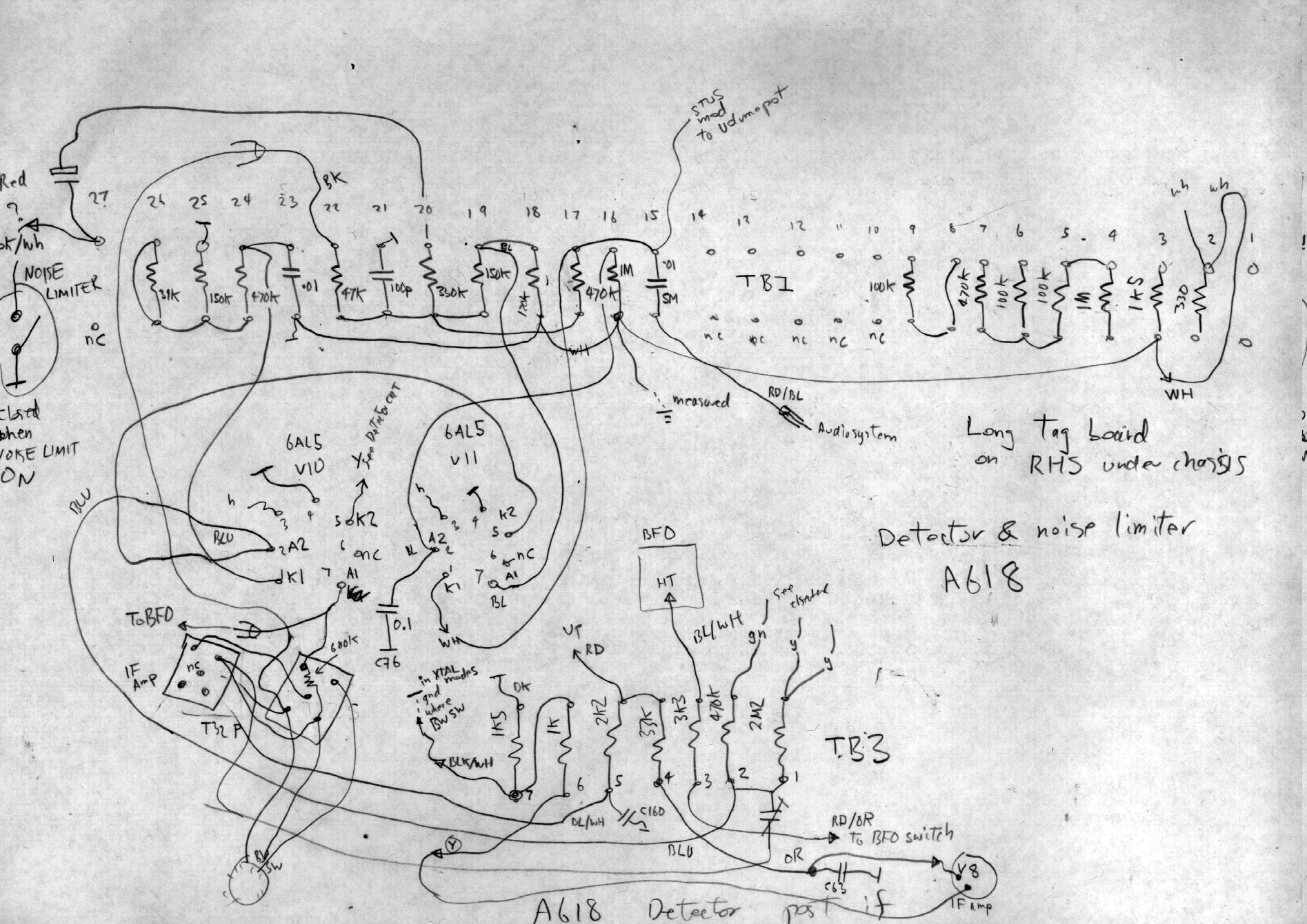
detector and noise limiter and under chassis tagboad RHS
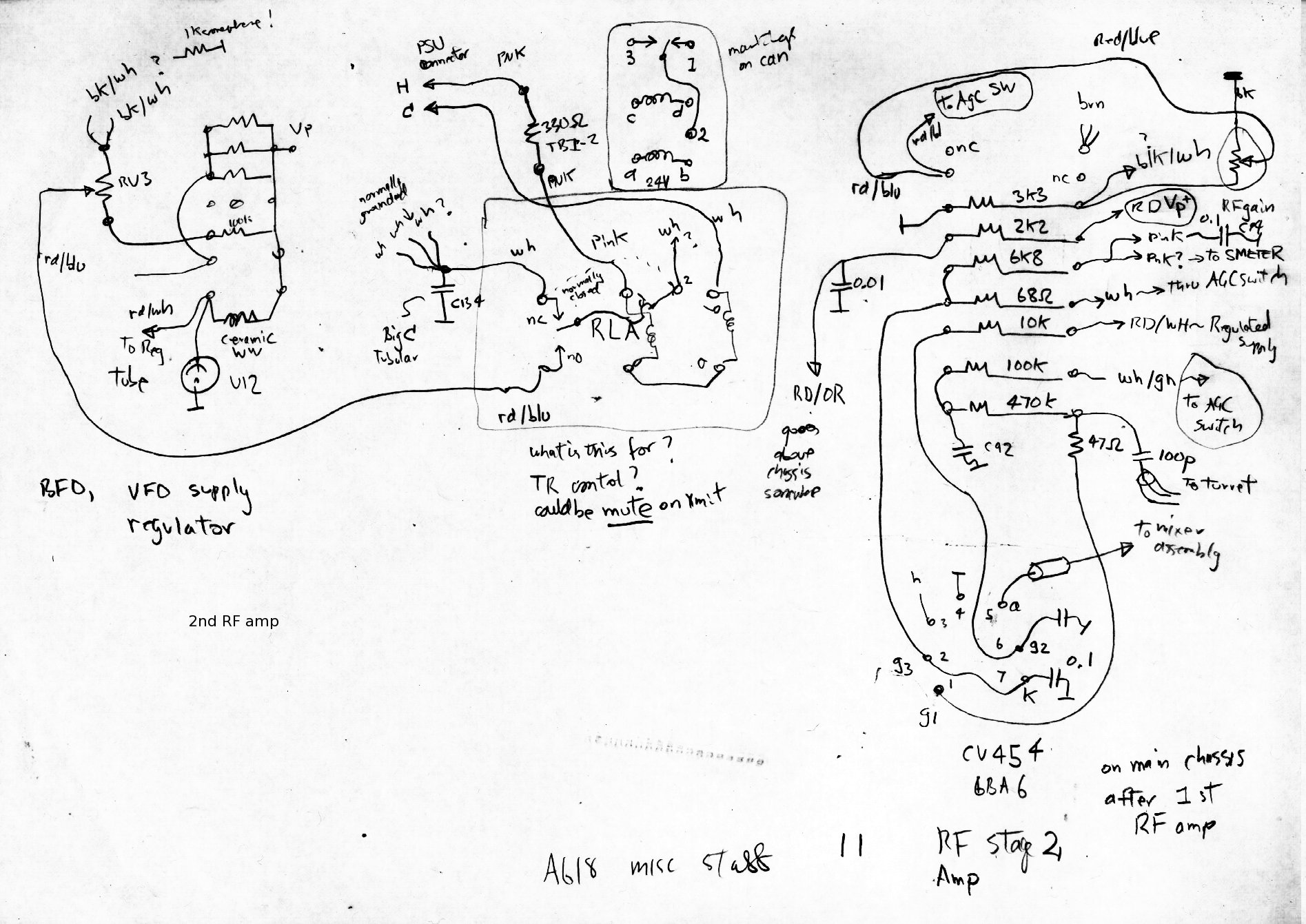
2nd RF amp, vfo regulator, mute relay
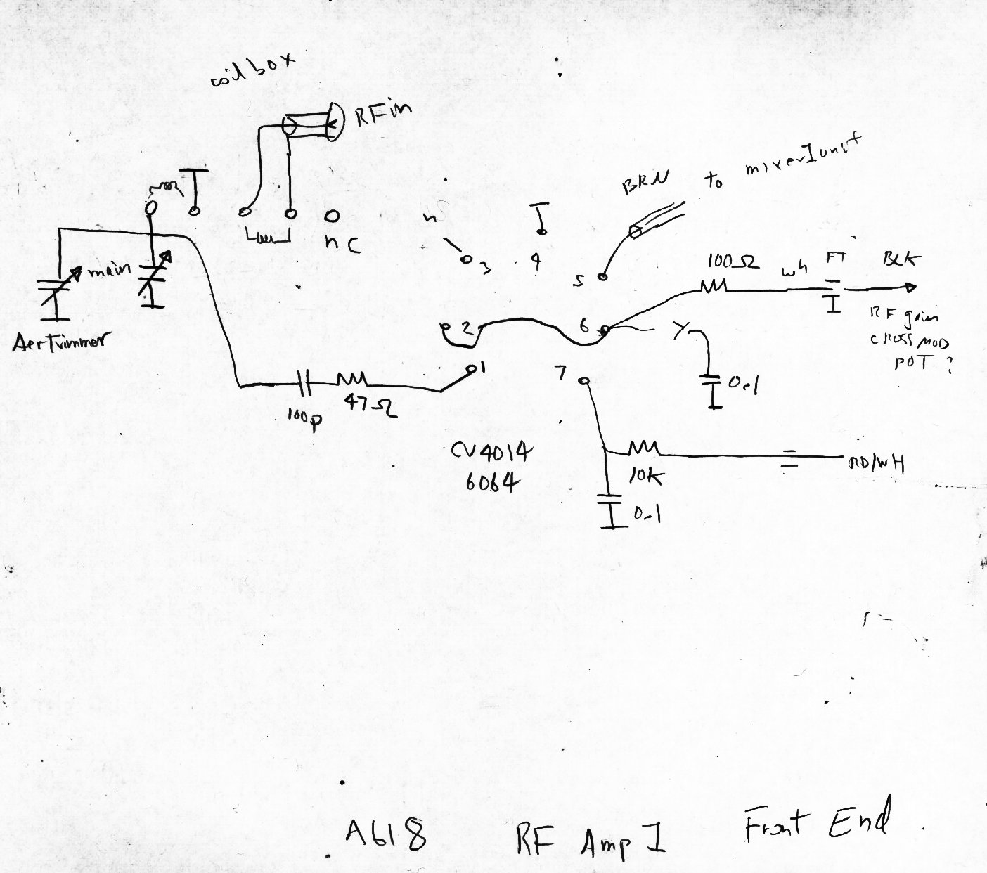
first rf amp
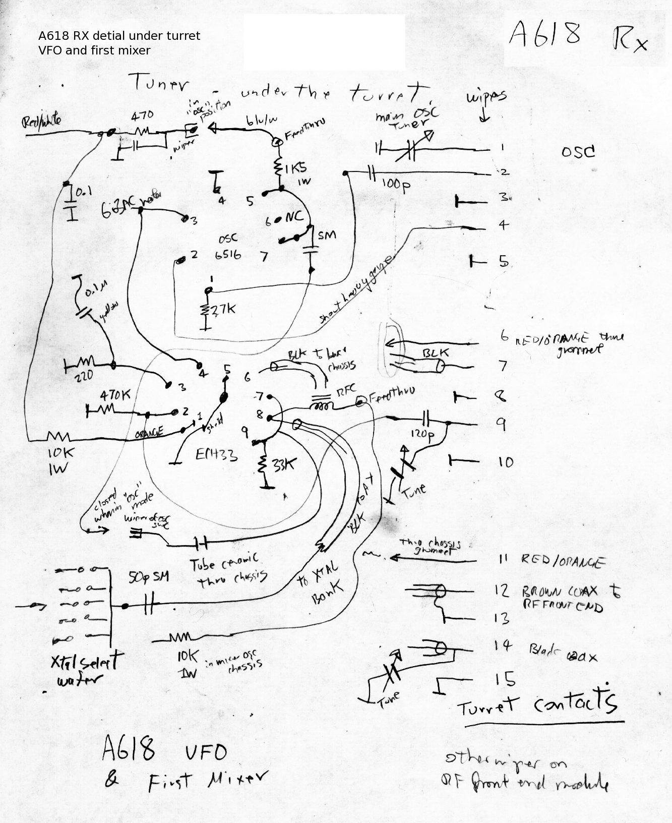
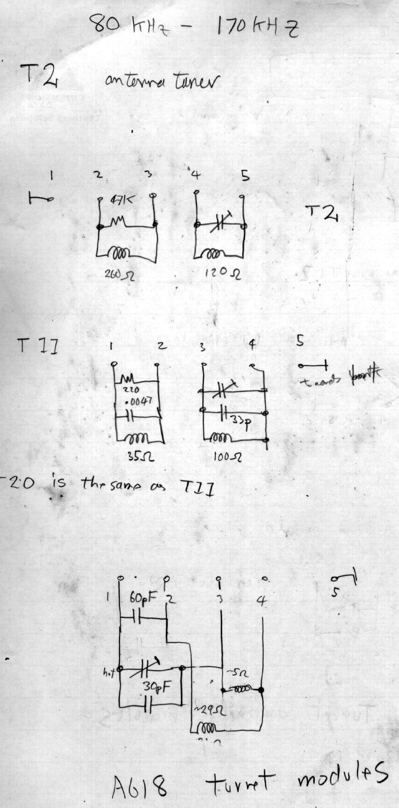
turret contacts, first mixer vfo
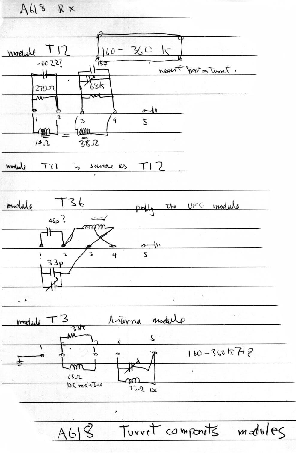
turret biscuits example
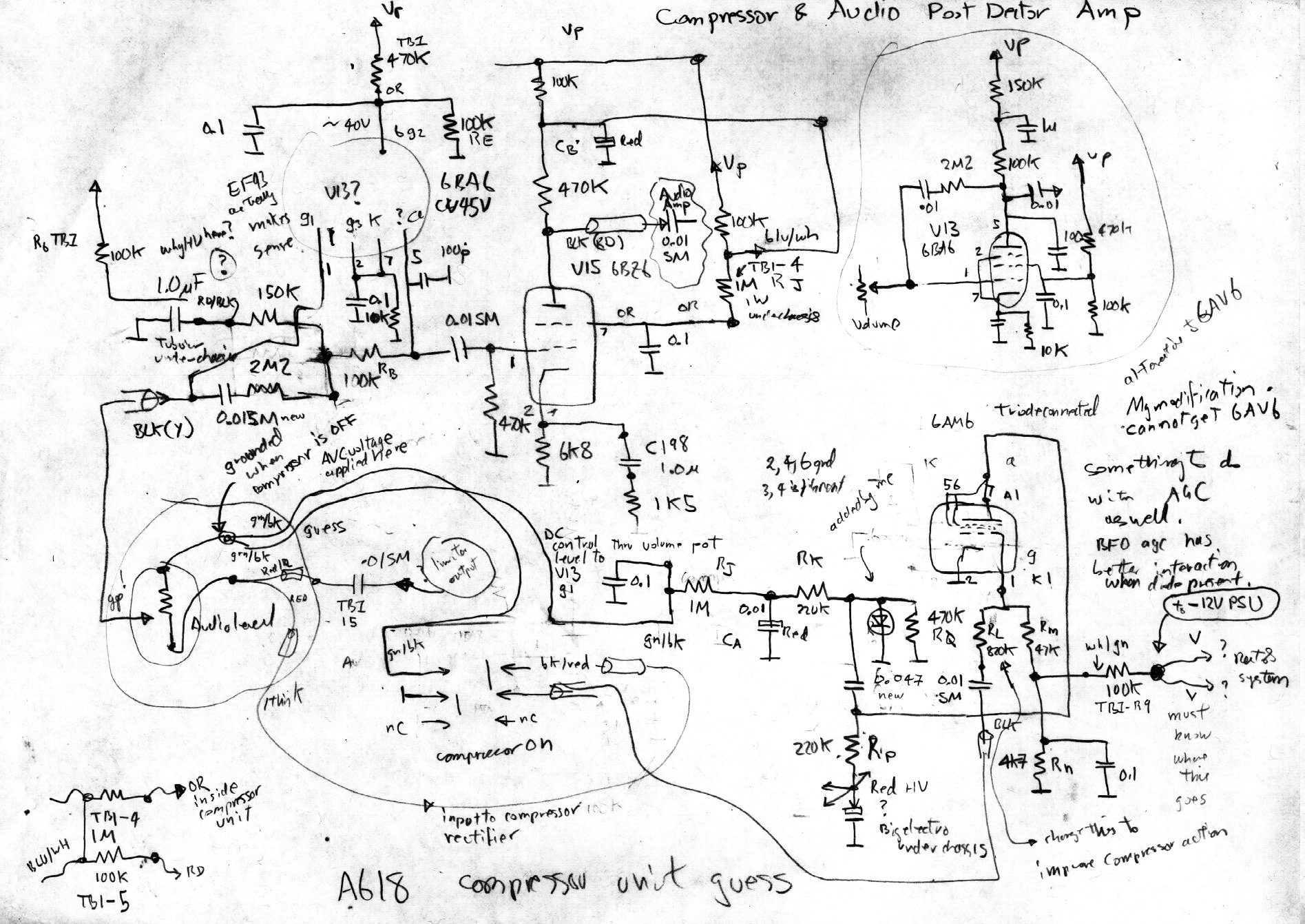
post detector af amplifier and audio
compressor.This contains my hamification. I could not find a
replacement 6AV6 triode diode so I have rewired it to use a 6AM6
triode connected as the audio agc driver and a silicon diode as audio
agc detector. This has worked well. I choose the 6AM6 because I have
many and it required the least amount of socket rewiring in a hard to
get to location.
My unit is powered from a high voltage
dc supply. It wants about 250 volts DC, 6.3VAC filament supply and a
negtive DC voltage source to supply negative bias for the agc system. I
have found that negative 12 volts is sufficient but I believe
that it officially should be negative 40 volts to get the full agc
range. The power connector has many more conductors than I have
yet mapped. The remote mute relay is controlled through the power
harness and a few other things that I havent got around to
understanding yet. They dont impact on simple normal operations.
I have owned this unit, serial number 0006, for 20 years now. It has
given little trouble over this time however in the last couple of years
there has been rapid deterioration. The unit is constructed with
one watt carbon composition resistors and nearly all resistors greater
than 10Kohms that are disipating any significant power have had to be
replaced as most have doubled or tripled their nominal resistance.
The biggest surprise was finding that audio interstage coupling
capacitors used were silver micro 0.01uF. Silver micas should
have NO leakage...right....nope your wrong. After 50 years these
devices have at least a mego-ohm leakage, some had 100K worth of
leakage. This completely deranges grid bias of suceeding stages.
Replacing these , and, all paper caps with polyesters restored
the audio compressor to life and the audio once again sounded clean.
Keep the turret contacts polished ,
dont use abrasives, bond paper is
sufficiently abrasive to get and nice shiny metal surface on the turret
bump contacts (silver metal!) . The original mil spec
valves with the CV number should still be serviceable....after fifty
years! mine are! Will YOU be serviceable in 50 years ? The
only valve that may cause some greif is the converter valves, CV2128
also known by the commercial equivalent of ECH81. They are very rare,
some may still exist in some hams bottle bank. The others have
common equivalents like 6BA6 et al. I could not find a 6AV6 to
fix the compressor so I have used silicon diodes and a 6AM6 pentode
wired up as a triode as a fucntional alternative. I think that when the
time comes to replace an ECH81 I will replace it with a TV
pentode/triode 9 pin valve. It should even have lower noise than the
ECH81 pentagrid.
The dial cord was orginally steel standed fine piano wire, I have
restrung this several times with heavy nylon fishing line. Its a
complete pain to restring but nylon will last 7 years even in the hot
interior.
Still to do:
First mixer and first if bandswitching. This is hard due to innaccesiblity in the chassis
2nd if bandwidth selection.
easier said than done. This complex wafer switch taxes my tiny mind too
hard. It works and I hope it stays working!
Fix band 3, for some reason it
has become deaf. No good for NDB dxing. Suspect a silver mica has gone
bad, however these bakelite units were not marked in indelible ink, the
markings have evaporated.
Hamifications to think about.
The radio does not have a product detector and BFO energy leaks
into the AGC. This makes SSB reception rather trying. The radios
performance on its highest band could be better, perhaps a
shock..horror solid state front end, mosfet, to replace the first
RF amp.
And the existential question? Do
I "restore" the radio hence no hamifications, or do I bend the orginal
design to my will and improve on some notable design deficiencies
especially the lack of product detector?