The Wireless Reception set R5223, the poor mans' Larkspur
ralph klimek may 2007
This web page is devoted to the Wireless Reception Set R5223 made by TCA Australia.
It contains the complete service manual, pictures and my complaints, gripes and notes about this radio.
Introduction.
The Reception Set R5223 is a receive only device. It covers
the entire HF spectrum from 1.5Mhz to 30Mhz in 30 odd bands. It was
designed to receive AM voice, CW, and MCW transmissions. It is all
valve based with an advanced double conversion super heterodyne design.
It lacks a product detector. it could be powered from a vehicle battery
or mains.
My connection with this set.
I acquired this radio from "The Lizard" VK3YRU nearly 30 years ago. It
had been heavily Hamified, perhaps the most objectionable Hamification
was the removal of the original military grade knobs on the front panel
for cheap-n-nasty placky consumer grade knobs. And it had been painted
baby blue. Yeech! I originally bought it for $20 on a what you
see is what you get transaction. It came with the manual ! and it wasnt
working.
I first saw sets of this kind for sale in the disposals store and
expressed interest in one. The Wise Old Ham warned me off it, saying
that I couldnt afford it.( I was 14 at that time ) That part was true,
they cost more that I was worth. I also could not have afforded to keep
it running!
I got the set working again, and it worked extremely well, but keeping it going was and is still a complete pain.
My notes and gripes.
Let me be the first to say that the electronic design of this radio had
left nothing to chance, it was good as the state of the Australian art
permitted in the early sixties, and some aspects were both very
conservative and very innovative. Coverage of the entire HF spectrum in
30 bands was unique and it wasnt a Collins or a Racal. It was
sensitive, a test lead jabbed in the antenna socket made it a good
general coverage shortwave radio. My gripes are many and
manifest. I had been spoiled, I was by then accustomed to Larkspur
build quality and the build quality of this radio was only slightly
better than consumer grade electronics. The components were thermally
underspecified, consumer grade electronic components had been used
instead of mil-spec devices. Somebody had tried very hard to make a
dependable and best of breed radio but clearly the bean counters and
management had won this battle and they produced a lemon instead; in
the way that bean counters and managers only can when they are
allowed to make engineering decisions. The only Larkspur like
element in this design was the fully sealed die-cast enclosure and
ruggedised front panel.
The maintenance philosophy of this set was like eighties computer
systems, fault diagnosis to the smallest FRU (Field Replaceable Unit).
The FRUs in this set were small sealed and soldered up metal cans, with
only the valves, control shafts and terminals exposed. The terminals
were not plugs and sockets ( ala Larkspurs ) but solder
terminals....this is arguably a good or bad thing depending on your
point of view. Actual Maintenance was restricted , by design, to valve
replacement, and if a component internal to one of these metal cans was
dead, you were compelled to replace the entire can. This is actually a
good operational model, but for the collector/restorer/enthusiast/Ham
is a total pain. It is thus totally impossible to probe the circuits. I
had to build a
valve socket extender so that I could measure the
voltages under the valve pins and infer the fault. The only concession
made to would be maintainers was a built in multimeter (complete with
probes!) and the ability to monitor the plate current of every valve or
assembly from a front panel control and the built in meter.
Practical maintenance for people like us requires you to open the tin
cans. This destroys the structural integrity of the can so you must be
carefully as controls are also attached to the cans and the cans dont
have anything like an internal sub-chassis. Much to my annoyance
and chagrin, where one watt resistors should have been used, quarter
watt resistors had been used, and of course they were all out of spec
or just burned. Cheap and nasty paper capacitors had been used
for bypasses but fortuneatly good quality silver micas used for
resonant elements and other places where the value of capacitance
mattered. The worst components used were tuned inductors in the IF
stages and the tuned IF. Never attempt to adjust these, they just
disintegrate ! I did and as a consequence had to build my own IF strip.
I have had to open every can and replace mostly everything. One
shouldnt speculate what negative impact this set had on actual
military operations...it could not have been good.
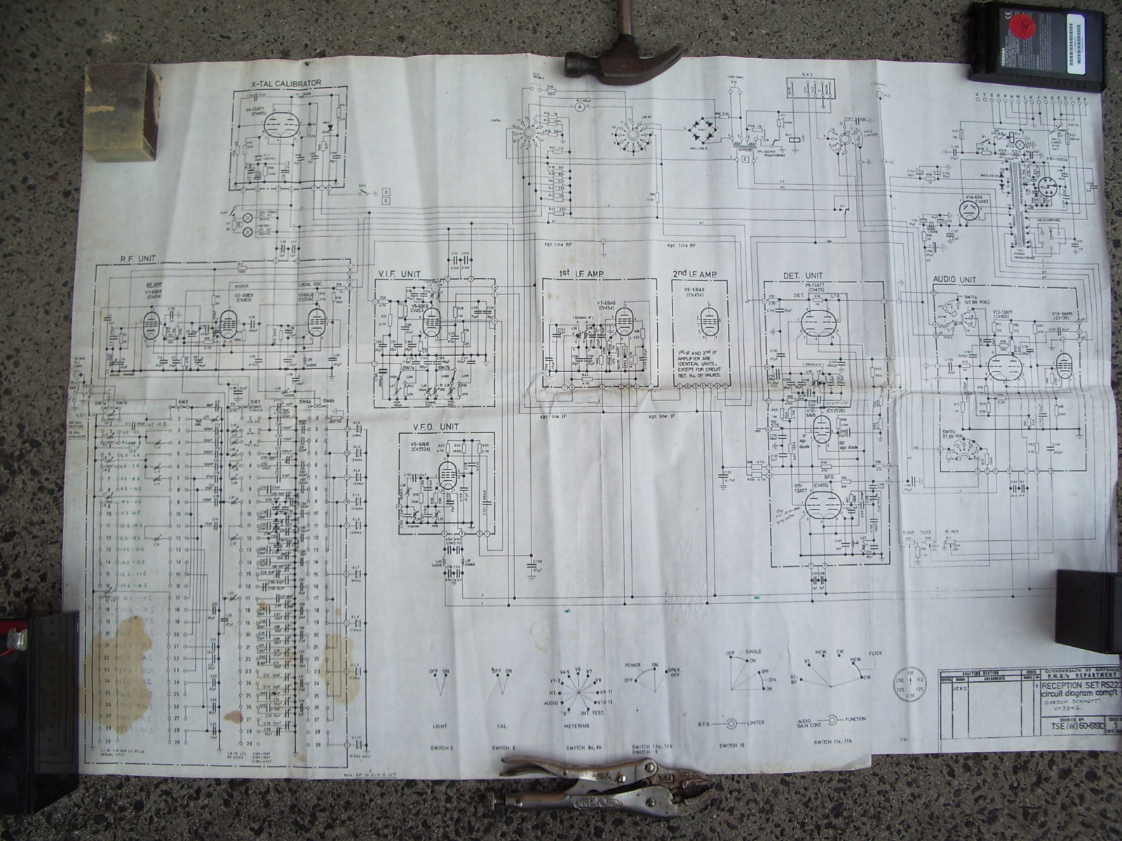
The circuit diagram I have only as a large fold out sheet and presented
here are pictures of it taken with a digital camera. The rest of
the manual is scanned on a old HP scanjet 2 and presented here. The
manual is very verbose and has an elaborate tune up procedure. In an
off the cuff way it mentions that the radio is fundamentally
unrepairable. Never be tempted to retune the IF or VIF inductors, they
will break. The RF unit inductors may be retuned without risk of
damage.
If you have one of these lemons, do take the trouble to restore it, you
will get a superb general coverage short wave radio out of your
efforts. Replace all paper capacitors with polyesters and any resistor
that has to dissipate any power , like screen grid resistors should be
wire wounds or 1 watt metal films , if you can get them. It used only
consumer grade valves, thats a pity but the upshot is that they are all
still available from ham bottle banks, only the 6AV6 and 6BE6 pentagrids may be
hard to get now. All the bottles have CV numbered mil-spec equivalents
and substitution is recommended by me.
My own Hamifications would be re-engineer the DETECTOR and AGC units so
as to provide a product detector. As it is, BFO injection upsets the
AGC requiring you to use the manual RF gain control. This mis-feature
is common even in the superior built Larkspur radios. The clever
feature of this radio is the use of only 9 crystals to generate all 29
of the first mixer master oscillator signals required for 30
separate bands. In them-thar days the cost of these crystals would have
been significant. So far I have had to rebiuld the IF amp, the detector
agc unit got a ceramic resonator i.f so it has now a very decent AM
general coverage response.
At this point in time, the radio is
not functional. It still works but it is now quite deaf and I have not
been able to pin down the reason. Everything works but there is a unit
that is not doing its job properly. Diagnosis is difficult
because the individual stage gains have not been properly documented,
allthough in the manual there is a half hearted attempt to do so.
See also the R5223 web page of
Ray Robinson VK2ILV
which has a very thorough and painstaking restoration of this
radio and some much nicer pictures as well. (my manual is better!)
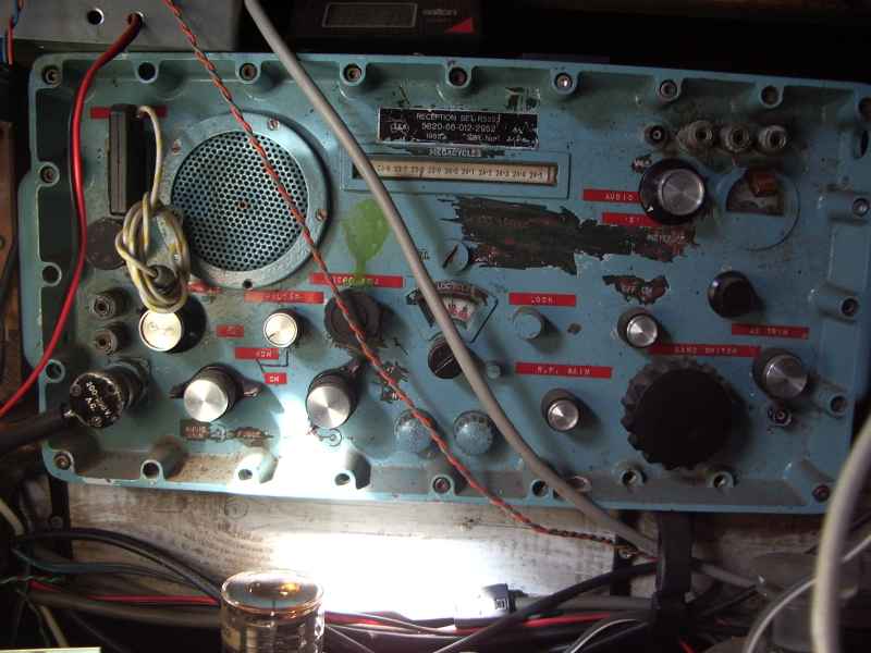
Reception Set SFT R5223, 5820-66-012-2952 1965 SER No (unreadable)
made by TCA Australia
Click me for hi resolution images of the inside of this radio.
Underneath the awful blue paint is
the original army green. Someone, certainly not me , substituted yucky
consumer knobs...lord knows why. Must have seemed a good idea at the
time. If I could scrape off that blue paint without damaging the
original I would.
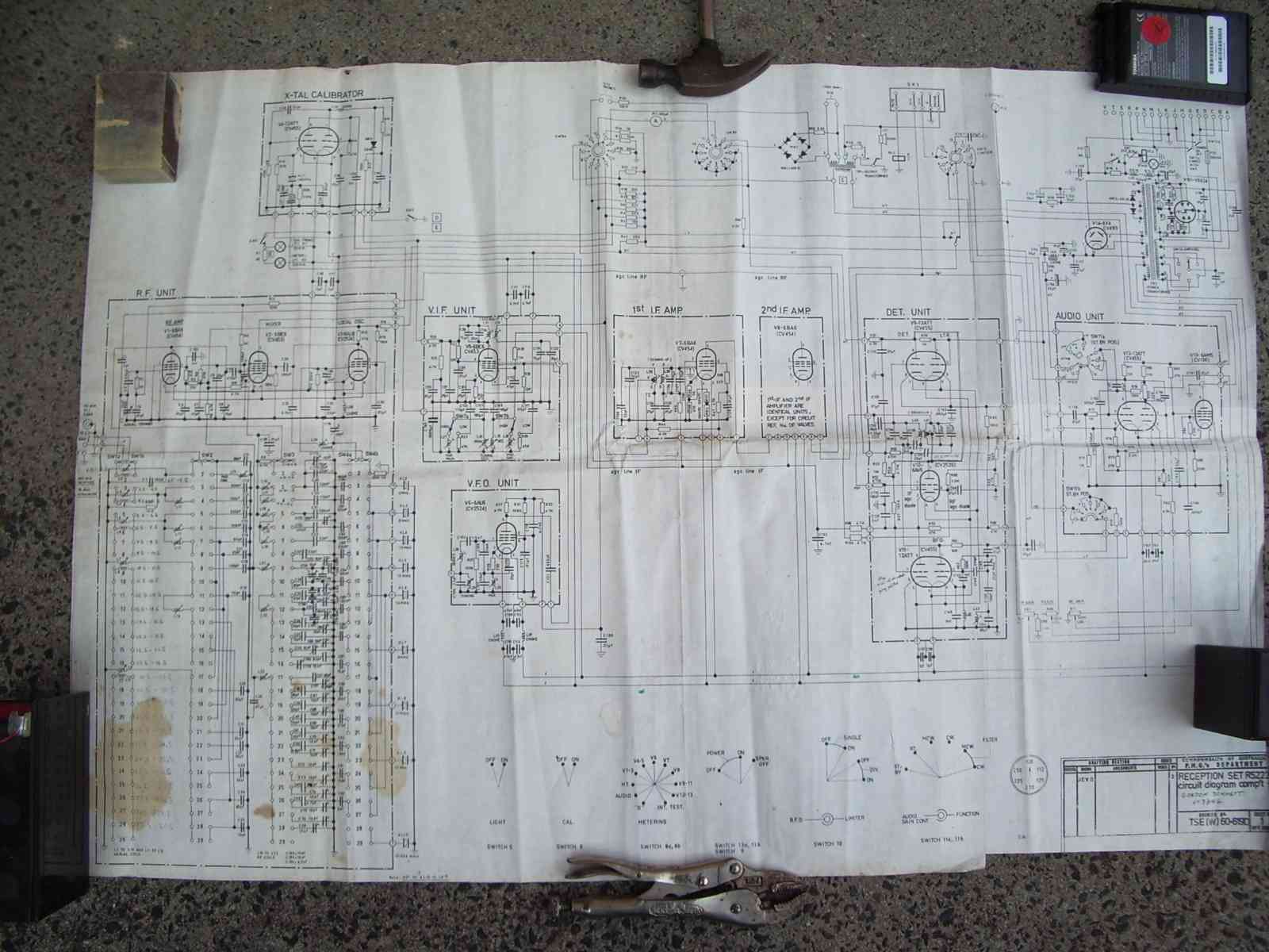
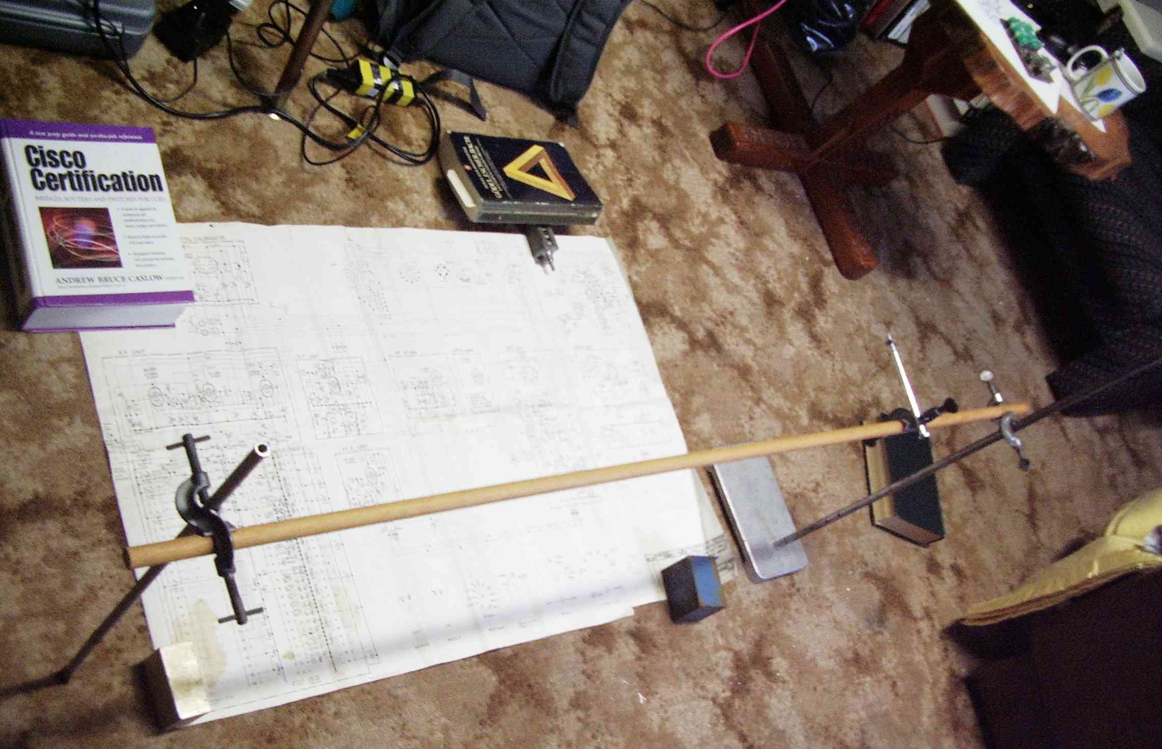
Improved large schematic pictures.
This view of the schematics was
photographed with a small pentax on this improvised travelling frame.
This permitted the camera to be at a fixed distance from the blueprint
for each picture. However when it came time to stitch the individual
images together I found that the little pentax optio is not a
process camera. Some assymetic scaling was required to get the
image portions to line up was required. I have left the image
portions in this tarball if you want to print your own paper versions
and stitch them together using traditional paper and scissors method.
And , here is the entire manual.
I had photocopies given too me when I purchased this nearly 30 years
ago. The copies came on that horrible old zinc oxide coated liquid
toner machines. The paper still has the unmistakable choking stench
that these machines emitted. The images were also rather lousy. They
have gone dark over the years but are still legible, not good enough
for OCR , so what you see is all you get. There are over 100
pages, so I will not html-alize them. Download the complete tarball
here. I have edited all of the images using the GIMP to clean them up,
and most are now actually readable. Now with all of 30 years worth of
grime are gone the total download size has also been reduced by
some 6 megabytes (at no extra charge!) if you have downloaded my
original tarball, do it again. It will be worth the wait. The
images have been cleaned up with the GIMP "dodge and burn tool" which
literally wipes away "grime" from grayscale images. This is the final
graphical edit of these files and just about all of them are now
printable and legible with a good graphics viewer. These images
will ultimately be set to RoyalSignals and the BAMA.
I will not put them in a PDF. The practice of taking each binary word
and re-encoding as textual hex bytes will bloat out this to
hundreds of Mbytes, its just not worth doing. If you are stuck with
poor old windows, there are many good free archiver programs which will
unpack a unix tarball.
Here are presented some of the more interesting and usefull pages.

this one has been cut and pasted together from assorted blue print cutlets


This image is only a low resolution thumbprint. Click on it to get the
high resolution blueprint. warning this image is big and may crash your
browser. Better to right click and save as... and view with a dedicated image viewer.

This is the only attempt in the official manual to document signal
levels to help troubleshoot under performing modules. Its not very good
and this is as good as it gets. They really wanted you to just get the
field replaceable unit. I suspect that even this page was an
afterthought.

This is a mosiac of seperate scanned images of the blue print.
The link below points to the seperate sheets to help you print
them out so you can cut and paste them into one continuous sheet.
click this line to get a tarball of the seperate block diagram mosiac parts

This table is in the manual tarball in its un-enhanced glory, in its original unreadable
glory. This image I have peered under a microscope to attempt to read
the original characters, I think I have recovered most of the data.
This table will help you to make sense of the way the VIF is
changed as a function of the selected band. The table also shows
the expected image responses, and also the crystal multiplier integers
for each band. The handwritten notes are my reading and guess of the
original text.
mod record:
added email sig Tue Nov 24 18:38:13 EST 2009