The Nerrigundah Catchment
The "Nerrigundah Catchment" is a 6ha experimental catchment located in the Williams River catchment on a property called Nerrigundah, approximately 11 km north-west of Dungog, NSW, Australia. The catchment runs east to west with a relief of 27 m. Hillslopes are typically 11% with a range from 3% to 22%, and the main drainage line has an average slope of 9% with a range from 1% to 17%. The catchment has an elevation of approximately 110 m Australian Height Datum (AHD) and is used for grazing of beef cattle.
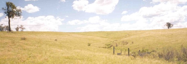
Figure 1: Photograph of the Nerrigundah catchmnet looking from east to west.
Nerrigundah has a temperate climate with a mean annual summer dominant rainfall of 1000 mm and a class A pan evaporation of 1600 mm. The maximum mean monthly rainfall occurs in January (147 mm) and the minimum occurs in July (37 mm), while the maximum mean monthly pan evaporation occurs in December (225 mm) and the minimum occurs in June (60 mm). Mean summer maximum and minimum temperatures are 30°C and 16°C respectively and mean winter maximum and minimum temperatures are 15°C and 6°C respectively.
To verify that the Nerrigundah catchment was producing anticipated soil moisture patterns in response to rainfall, a transect across the catchment was monitored from June 17 1996 to September 25 1996. Soil moisture measurements were made every 10 m with the Soil Moisture Equipment Corporation TRASE TDR System using 15 cm connector TDR probes. The standard TRASE calibration was used to determine the volumetric soil moisture content from the measured dielectric constant. Soil moisture measurements were made on Julian days 169, 178, 184, 197, 201, 211, 234 and 269. As no rainfall measuring device had been installed in the catchment at this time, rainfall measurements were obtained from two nearby rain stations, located on either side of the Nerrigundah catchment.
The Nerrigundah experimental catchment was permanently instrumented from October 12 1996 through to October 20 1998, for soil moisture content, soil temperature, runoff, rainfall and meteorological data. The permanent instrumentation was located such that lateral redistribution of soil moisture would be negligible, and measurements for estimating the surface fluxes (precipitation/evapotranspiration) representative of the entire catchment. Therefore, the permanent instrumentation was located in a level location in the upper reaches of the catchment. Monitoring of the spatial variation in soil moisture data could not be performed economically using permanent instrumentation. Hence, the spatial and temporal variation of both near-surface soil moisture content and soil moisture over the soil profile was extensively monitored during an intensive field campaign from August 27 1997 to September 22 1997. Monitoring of soil moisture profiles was continued from September 22 1997 to October 20 1998 on a less frequent basis. Soil moisture profiles were measured on August 22 1997 to provide background soil moisture values for the intensive field campaign.
Permanent instrumentation in the Nerrigundah catchment consisted of a Campbell Scientific automatic weather station which monitored: relative humidity and air temperature; soil temperature at 0.5, 1, 2, 4, 6, 8, 12, 16, 24, 32 and 40 cm depths using thermocouples; soil heat flux at 2 and 12 cm depths using soil heat flux plates; atmospheric pressure; precipitation; net radiation; wind speed; and soil moisture content at a depth of 5 cm using a Campbell Scientific CS615 probe inserted horizontally, providing a soil moisture measurement over a layer thickness of approximately 4 cm. Apart from rainfall, all measurements were made at 1 minute intervals, and the average was logged every ten minutes. Rainfall was recorded for each tip of the 0.2 mm tipping bucket. The total soil profile depth of this location was approximately 46 cm.
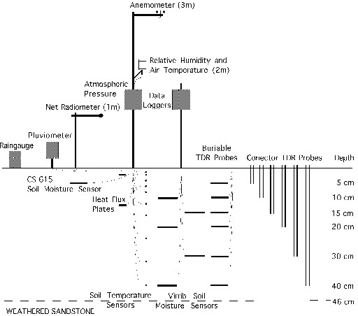
Figure 2: Schematic illustration of the permanent instrumentation set-up.
The soil moisture profile near the weather station was continuously monitored using five Virrib soil moisture sensors installed horizontally at depths of 10, 15, 20, 30 and 40 cm, providing soil moisture measurements over a layer thickness of 12 cm. These measurements were logged every 15 minutes. In addition, soil moisture measurements were made in this same location on a fortnightly basis, using horizontally inserted buriable TDR probes and vertically inserted connector TDR probes. Buriable TDR probes were installed at depths of 5, 10, 15, 20, 30 and 40 cm, providing an average soil moisture measurement over a layer thickness of approximately 4 cm. The connector TDR probes gave an average soil moisture measurement over depths of 0-5, 0-10, 0-15, 0-20, 0-30 and 0-40 cm, being the length of the probe. The TDR system used was the Soil Moisture Equipment Corporation TRASE TDR, using the standard TRASE calibration to determine the volumetric soil moisture content from the measured dielectric constant. The minimum depths at which the Virrib and buriable TDR probes could be installed without causing a loss of accuracy were 10 cm and 5 cm respectively. The vertically inserted connector TDR probes were not installed until April 24 1997 and the Campbell CS615 soil moisture sensor was not installed until May 8 1997.
A 1'6" partial flume was installed at the catchment outlet to monitor surface runoff. Discharge was monitored by measuring the water level in a stilling well to the side of the flume with a water level pressure sensor.
A second pluviometer was located at the flume, and four collecting rain gauges were distributed throughout the catchment to check the spatial variability of rainfall. Collecting raingauges were located at the weather station, flume, and one either side of the catchment at approximately half way between the flume and weather station. Collecting raingauges were recorded approximately fortnightly from December 31 1996. During the intensive field campaign from August 27 1997 to September 22 1997, collecting raingauges were recorded every two to three days.
For a full description of the experimental set-up and data collected see Chapter 9 (31577kB pdf) of:
Walker, J. P., 1999. Estimating Soil Moisture Profile Dynamics From Near-Surface Soil Moisture Measurements and Standard Meteorological Data. PhD Thesis, Department of Civil, Surveying and Environmental Engineering, The University of Newcastle.
This data was collected as a twin experiment to the Tarrawarra data set and should be referenced as:
Walker, J. P., Willgoose, G. R. and Kalma, J. D., 2001. The Nerrigundah Data Set: Soil Moisture Patterns, Soil Characteristics and Hydrological Flux Measurements. Water Resources Research, 37(11): 2653-2658. (274kB pdf) Copyright 2001 American Geophysical Union
Two Digital Elevation Models (DEMs) were obtained for the Nerrigundah catchment: (i) accurate and (ii) published. The accurate DEM data was obtained from a ground survey with total station while the published DEM was obtained from digitising the contours on 1:25000 series topographical maps and was provided by the Land Information Centre, Bathurst, Australia.
Both sets of elevation data are available as point data *.xyz and gridded data *.grd on both the Australian Map Grid *-amg.* and local *-local.* coordinate systems. The parameters for transforming between the the two coordinate systems are given here.
All files have data in metres and have elevations on the Australian Height Datum.
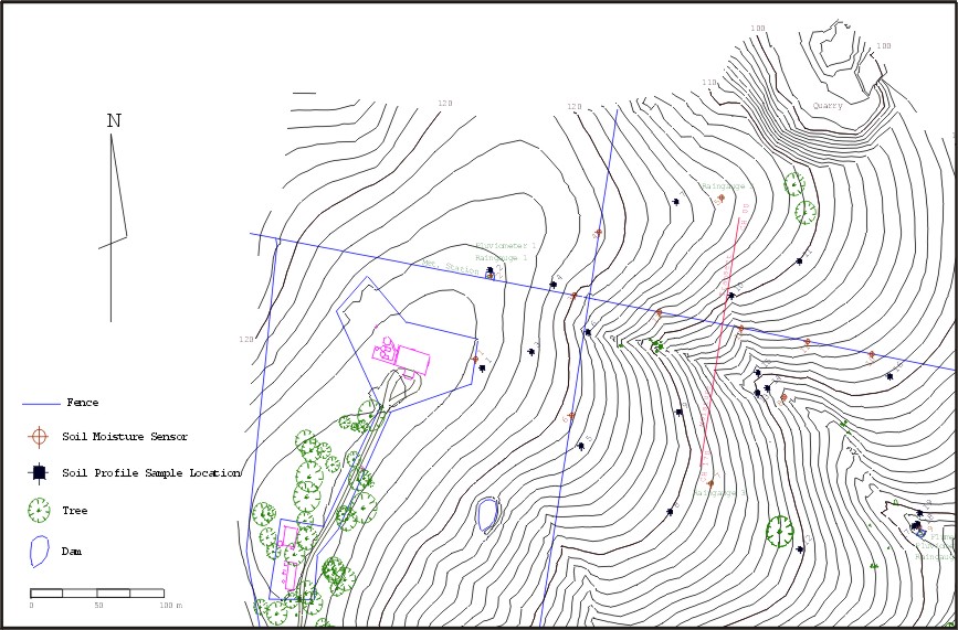
Figure 3: Accurate DEM of the Nerrigundah catchment showing location of sensors soil sample sites.
The soil moisture maps are 15 cm TDR data collected on a 20 m regular grid over the Nerrigundah experimental catchment during the intensive field campaign in September 1997. This was achieved using the University of Melbourne's terrain data aquisition system. A total of 7.5 mm of rain was recorded during the collection of soil moisture data on 19 September. Coordinates are given on the local coordinate system. Plots of this data are given in Appendix C (1451kB pdf) of Walker (1999).
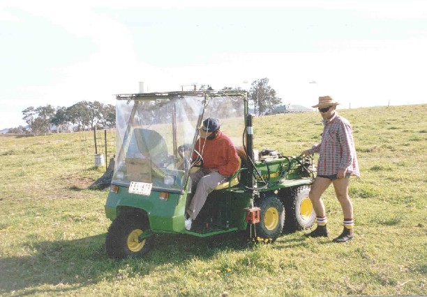
Figure 4: The "Green Machine" terrain data acquisition system used for mapping of surface soil moisture data.
The file is given as: East (m), North (m) and Moisture Content (% v/v)
File: TDR*.dat where * = date (ddmm) for which data was collected
The connector TDR data was collected at 13 different locations throughout the catchment, including the weather station. Plots of this data are given in Appendix B (2347kB pdf) of Walker (1999). Comparison of connector TDR data with thermogravimetric measurements showed that the standard calibration was adequate for the 10 and 15 cm probes lengths, whilst the 5 cm probe lengths yielded a noisy response (Walker, 1999). The calibration of longer TDR probes was not evaluated due to the destructive nature and labout intensiveness of the testing, the number of calibration data values required to make conclusive statements regarding accuracy, and the good agreement for the shorter probes.
Table 1: Australian Map Grid (AMG) coordinates of soil moisture profile measurement sites and total depth of soil.
| Profile | Total Depth (mm) | AMG Easting (m) | AMG Northing (m)| AHD Elevation (m) |
| 1 | 450 | 378 931.6 | 6 423 427.1 | 124.81 |
| 2 | 450 | 378 942.2 | 6 423 483.1 | 124.33 |
| 3 | 320 | 379 005.4 | 6 423 471.0 | 119.92 |
| 4 | 450 | 379 023.1 | 6 423 513.6 | 121.32 |
| 5 | 350 | 379 115.1 | 6 423 538.5 | 115.61 |
| 6 | 320 | 379 004.8 | 6 423 390.8 | 119.20 |
| 7 | 520 | 379 110.6 | 6 423 347.2 | 108.03 |
| 8 | 1300 | 379 164.7 | 6 423 405.9 | 97.74 |
| 9 | 850 | 379 267.9 | 6 423 321.1 | 88.30 |
| 10 | 400 | 379 230.3 | 6 423 435.9 | 102.50 |
| 11 | 520 | 379 181.5 | 6 423 443.6 | 104.49 |
| 12 | 320 | 379 131.4 | 6 423 451.4 | 105.96 |
| 13 | 340 | 379 069.6 | 6 423 461.1 | 112.62 |
|
The profile coordinates given in Table 1 may be transformed to the local coordinate system using the transformation parameters.
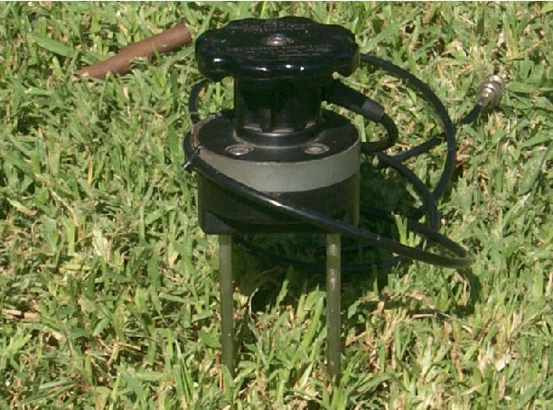
Figure 5: Connector TDR soil moisture sensor.
The file is given as: Date (dd/mm/yy), Time (hh:mm), MC#1 (% v/v), ... MC#N (% v/v) for depth given in cm. Missing data is indicated by -999 in the data file.
File: cTDR-*.dat where * = profile number from 1 to 13
The burriable TDR data was collected throughout the soil profile at the weather station. Plots of this data are given in Appendix B (2347kB pdf) of Walker (1999).
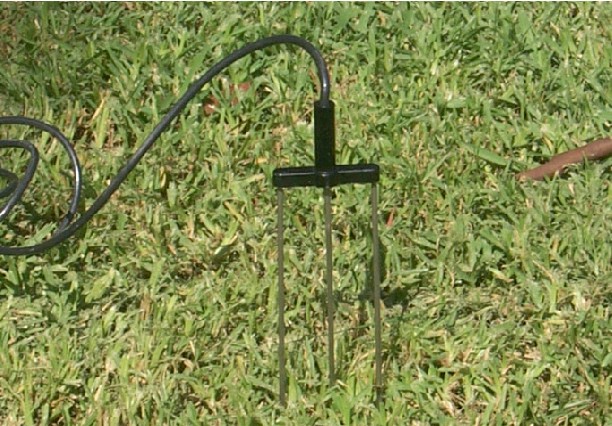
Figure 6: Buriable TDR soil moisture sensor.
The data is given as: Date (dd/mm/yy), Time (hh:mm), bTDR @ 5cm (% v/v), bTDR @ 10cm, bTDR @ 15cm, bTDR @ 20cm, bTDR @ 30cm, bTDR @ 40cm
File: bTDR.dat (6kB)
The virrib data was collected throughout the soil profile at the weather station. Plots of this data are given in Appendix B (2347kB pdf) of Walker (1999).
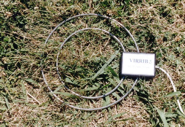
Figure 7: Virrib soil moisture sensor.
The data is given as: Time (day of year), Virrib#1 @ 10cm (% v/v), Virrib#2 @ 15cm, Virrib#3 @ 20cm, Virrib#4 @ 30cm, Virrib#5 @40cm
File: virrib.* where * = year (yy)
The CS615 reflectometer data was collected near the soil surface at the weather station. This data is included in the meteorological data. Plots of this data are given in Appendix B (2347kB pdf) of Walker (1999).
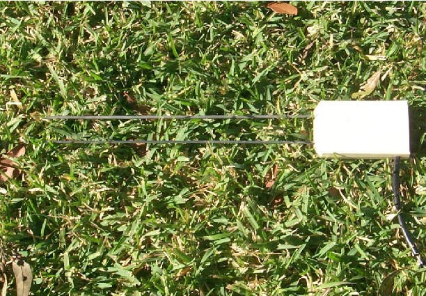
Figure 8: CS615 reflectometer soil moisture sensor.
The soil temperature data was collected throughout the soil profile at the weather station. Plots of this data are given in Appendix B (2347kB pdf) of Walker (1999).
The data is given as: Time (day of year), Temp @ 0.5cm (deg C), Temp @ 1cm, Temp @ 2cm, Temp @ 4cm, Temp @ 6cm, Temp @ 8cm, Temp @ 12cm, Temp @ 16cm, Temp @ 24cm, Temp @ 32cm, Temp @ 40cm
File: soiltemp.* where * = year (yy)
Runoff was monitored at the catchment outlet. Plots of this data are given in Appendix B (2347kB pdf) of Walker (1999).
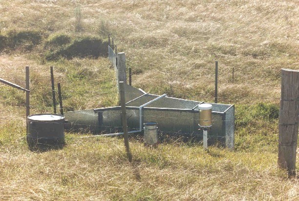
Figure 9: Partial flume and raingauges located at the catchment outlet.
The data is given as: Time (day of year), Water Level (mm), Discharge (L/s)
File: discharge.* where * = year (yy)
Rainfall was monitored using pluviometers at two locations; the weather station and the flume. This rainfall data was recorded as the time for each tip of the 0.2mm tipping bucket. Plots of this data are given in Appendix B (2347kB pdf) of Walker (1999).
The data is given as: Time (day of year), Rainfall Amount (mm)
File: pluvio?.* where ? = pluvio number 1 (weather station) or 2 (flume) and * = year (yy)
Rainfall was monitored using collecting raingauges at four locations; the weather station, the flume, and midway on either side of the catchment. This rainfall data was recorded as the total accumualtion between the previous recording and the current recording. Plots of this data are given in Appendix B (2347kB pdf) of Walker (1999).
This data is given as: Date (dd/mm/yy), Gauge#1 (mm), Gauge#2, Gauge#3, Gauge#4
File: raingauge.* where * = year (yy)
Meteorological data was monitored using a Campbell Scientific automatic weather station in the upper reaches of the catchment. Plots of this data are given in Appendix B (2347kB pdf) of Walker (1999).
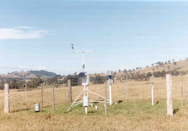
Figure 10: Photograh of weather station set-up.
This data is given as: Time (day of year), Soil Heat Flux @ 2cm (W/m2), Soil Heat Flux @ 12 cm (W/m2), Net Radiation @ 1m (W/m2), Relative Humidity (%), Air Temp @ 2m (deg C), Atm. Pressure (KPa), Wind Speed @ 3m (m/s), Penman-Monteith Potential Evap. (mm/d), CS615 Soil Moisture @ 5cm (% v/v)
File: metdata.* where * = year (yy)
Eddy correlation data was collected during the intensive field campaign at the Nerrigundah experimental catchment in September 1997.
This data is given as: Time (day of year), Cumulative Eddy Correlation Evapotranspiration (mm), Cumulative Penman-Monteith Potential Evapotranspiration (mm)
File: ed*.dat where * = Julian day of year for which the data was collected
Surface roughness measurements were made at 5 locations for each of two days during the intensive field campaign in September 1997 using a 1 m long drop pin profiler with a pin separation of 25 mm. Two sets of 1 m measurements were made in, north south, east west, and north east - south west directions, at each of the 5 locations. The roughness measurements were made near soil moisture profiles 2, 5, 7, 8 and 9. This data is plotted in Appendix D (166kB pdf) of Walker (1999). Surface roughness measurements provide a measure of the depression storage in the catchment.
A visual inspection of the Nerrigundah catchment indicated that the spatial distribution of surface roughness was uniform, apart from the main drainage line and steeper portions of the site. These portions were slightly rougher as a result of cattle grazing. This increased roughness in the gully is also seen in the roughness measurements made near soil moisture profile number 8. However, there is a wide variation in the roughness measurements, even for consecutive surface roughness profile segments at the same site, for the same direction, and for the same day.
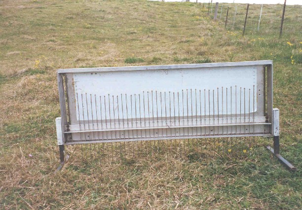
Figure 11: Drop pin profiler used for surface roughness measurements.
This data is given as: Distance along profile (cm), Elevation (cm)
File: *?#-!.dat where * = Julian day of year; ? = direction (ie. north-south, east-west, etc.); # = surface roughness profile number 1 to 5; ! = surface roughness profile segment 1 or 2
This is the preliminary monitoring data for the Nerrigundah Experimental Catchment, including transect monitoting of soil moisture using 15 cm connector TDR probes (TDR.dat), rainfall at Chichester (chirain.dat) and rainfall at Dungog Post Office (dporain.dat). The location of this transect within the Nerrigundah catchment is indicated in Figure 3.
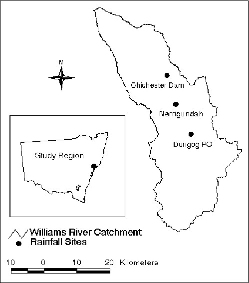
Figure 12: Location of raingauges with respect to the Nerrigundah catchment.
Transects of soil moisture measurements were made with the 15 cm connector TDR probes every 0.5 m for a distance of 25 m, under both saturated and somewhat drier conditions. The measurements made under drier conditions were also made in two perpendicular directions. Transects were also made with a measurement spacing of 0.1 m for a distance of 5 m. Measurements were made in an approximately level area near the permanent instrumentation in the top of the catchment, to minimise any effects from lateral redistribution.
This data is given as: Distance along Transect (m), Soil Moisture Content (% v/v)
File: *-?.dat where * = date (ddmmyy), ? = direction a (accross slope) or d (down slope)
Soil characterisation of the Nerrigundah catchment was undertaken from 19 soil cores retrieved from throughout the catchment using the soil coring capabilities of the "Green Machine". The soil coring device is capable of taking a minimally disturbed soil core of 55 mm in diameter and 800 mm in length. The soil corer consists of a rigid steel tube with one end tapered such that the sharpened cutting edge cuts a soil core slightly smaller than the inside diameter of the tube, thus minimising friction and smearing of the soil sample by the tube wall. The tube also has a slight bulge near the base of the taper that compacts the soil around the tube, thereby reducing the insertion force by minimising the friction against the outside of the tube. As the majority of soil within the Nerrigundah catchment has a depth of less than 600 mm, these soil cores gave a view of the entire soil profile at their individual location.
(a)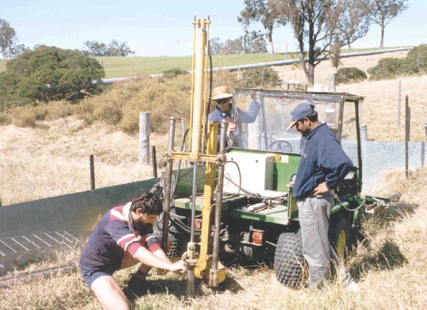 (b)
(b)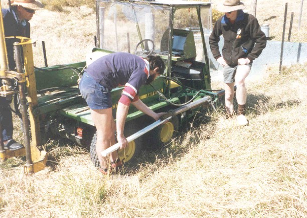
Figure 13: The "Green Machine" in a) soil core retrieval and b) soil core extraction modes.
Total soil depth was determined by measuring the soil cores retrieved using the "Green Machine". Where the soil depth exceeded 800 mm, further probing was undertaken to estimate the total soil depth. The AMG coordinates for soil core locations and the total soil depth at those locations are given in Appendix B (2347kB pdf) of Walker (1999). Soil depth was also estimated from probing with a 6 mm steel rod at profile soil moisture measurement sites, with depths and locations given above. Additional soil depths were determined from probing on a 40 m x 40 m grid during a period when the soil was moist. These measurements are given in Appendix B (2347kB pdf) of Walker (1999). The grid used was coincident with that used for near-surface soil moisture measurement with the "Green Machine" during the intensive field campaign. Additional measurements were made on a 20 m x 20 m grid for the area in the vicinity of the main drainage line.
The soil profile was described according to its horizons by the Northcote Factual Key Soil Classification System. Thicknesses of soil horizons were noted where identifiable, and the soil core dissected into its horizons for laboratory assessment. Where the A1 horizon was too shallow to give a large enough soil sample for laboratory testing by itself, the A1 and A2 horizons were combined. The laboratory testing for all 19 soil cores included bulk density, porosity, organic matter content and particle size analysis (237kB pdf). In addition, the quartz content was determined for the core taken near the weather station. Saturated hydraulic conductivity was estimated from field testing with the Guelph permeameter and double ring infiltrometer measurements. These data are given in Appendix B (2347kB pdf) of Walker (1999).
(a)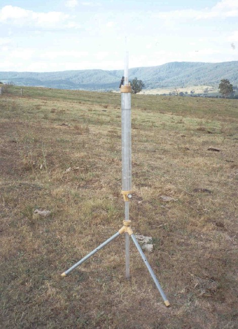 (b)
(b)
Figure 14: The a) Guelph permeameter and b) double ring infiltrometer.
You can download the entire data set and the accompanying documentation as zipped files. However, reference should still be made to this website for correct interpretation of the data files.
The Nerrigundah catchment is owned by John and Margaret Russell who have provided free access to their land and willing cooperation throughout the project.
Assistance in the field has been provided by Lyndon Bell, Rodger Grayson, Greg Hancock, Andre Kable, Jetse Kalma, Michael Kendal, Andrew Krause, Hemantha Perera, Mark Scanlan, Mark Thyer, Wendy Walker, Andrew Western, Garry Willgoose, Craig Wood and Scott Wooldridge.
|