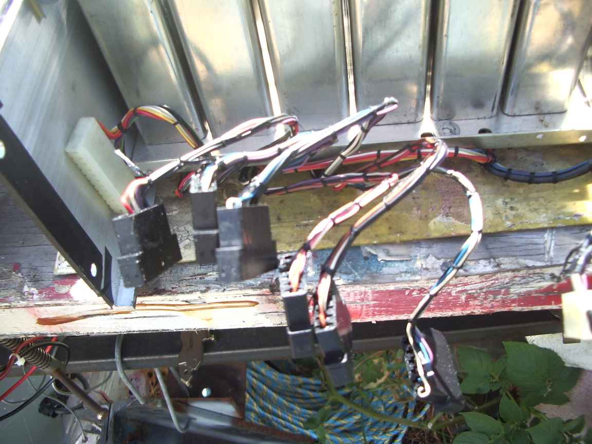
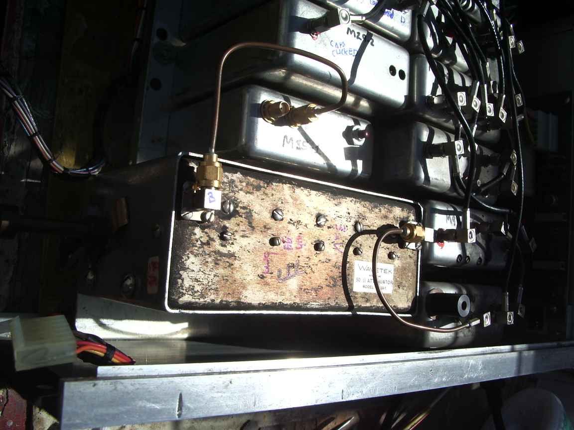
well worth saving from landfill
| restoration of a wavetek 3000 signal generator |
| by ralph klimek 2014 epilogue 2020 |
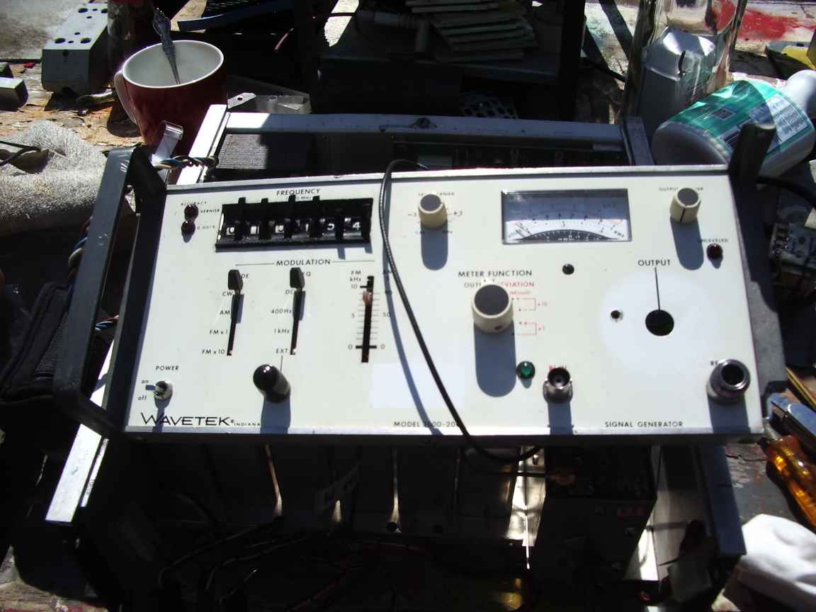
| The wavetek 3000 is a late seventies advanced multi PLL signal generator with coverage from 10Mhz to 500Mhz and numerous options for coverage and modulation methods. |
| This unit had been recovered from a dumpster and was non functional. Recently a poor quality manual has been found on the internet. I have extracted the images from this source and cleaned them up using the GIMP. |
| The
recovered manual was used to find the many faults that were present and
still present with this unit. My advice to people finding one
these units at a flea market or dumpster is to leave it there. There
are too many problems with this unit due to the serviceman un-friendly
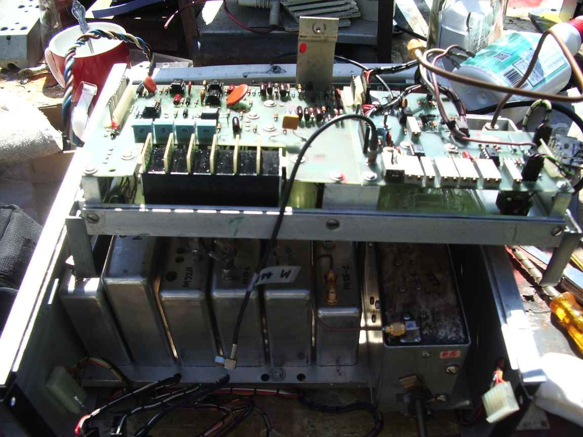
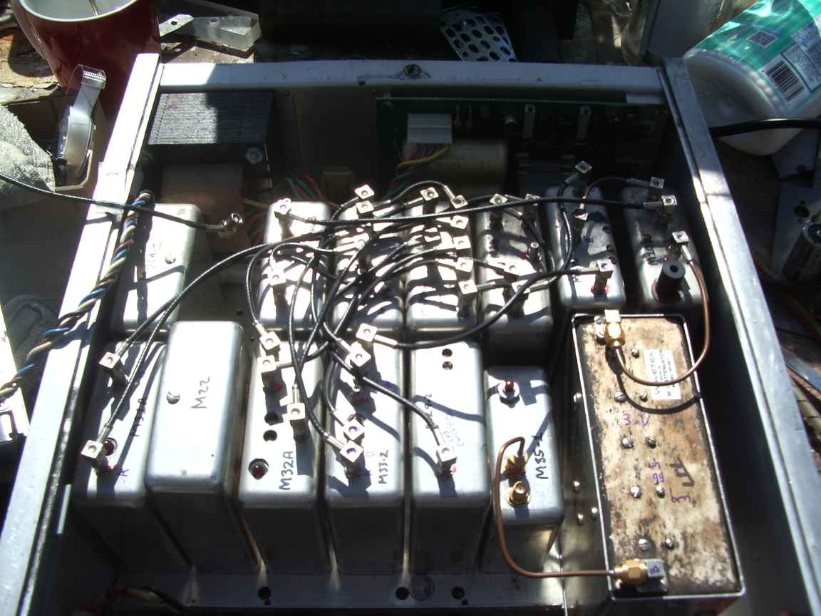
construction methods, most notably needing to remove and open up
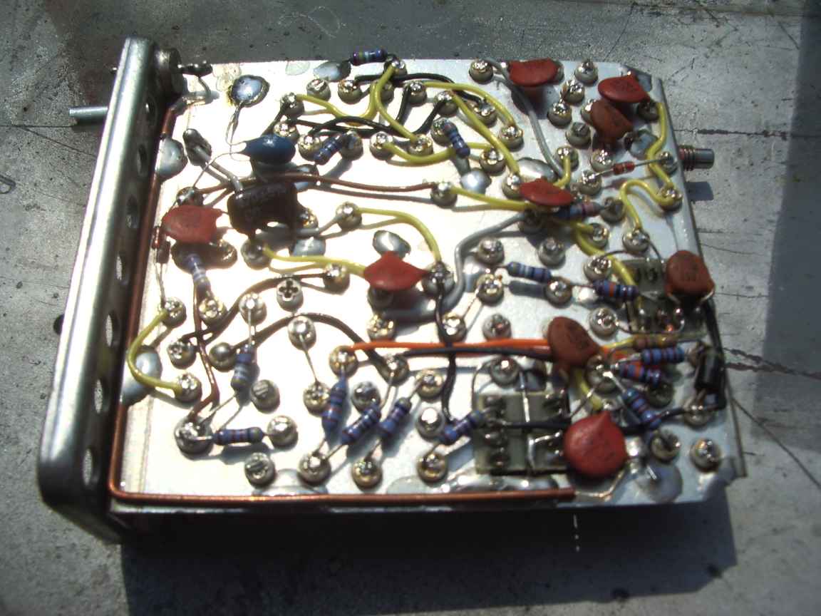
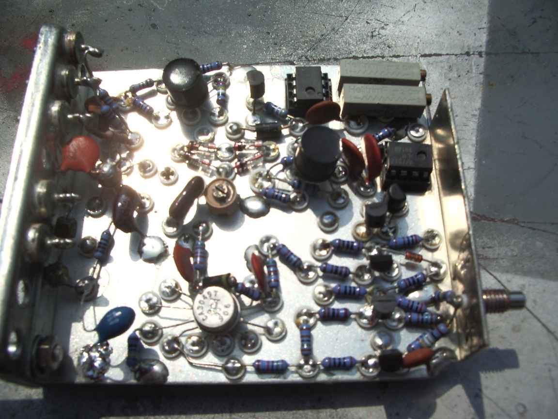
numerous tin cans to get at the circuits. Mine has been brought
back to life in as far as the unit produces a constant level frequency
stable output , that is, alas only loosely related to the thumbwheel
settings ! it also had numerous inherent implementation issues that were beyond tolerance or repair. |
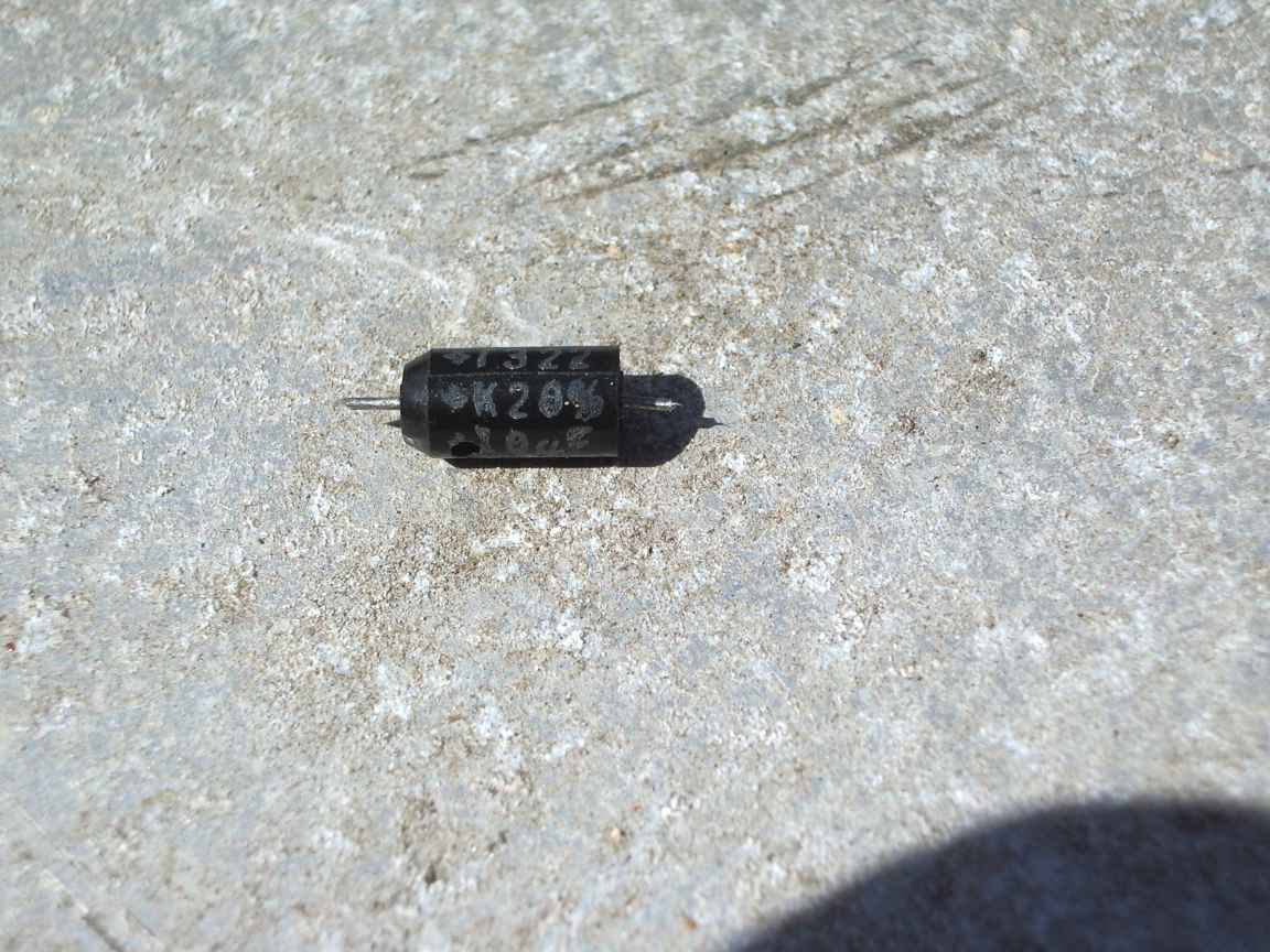
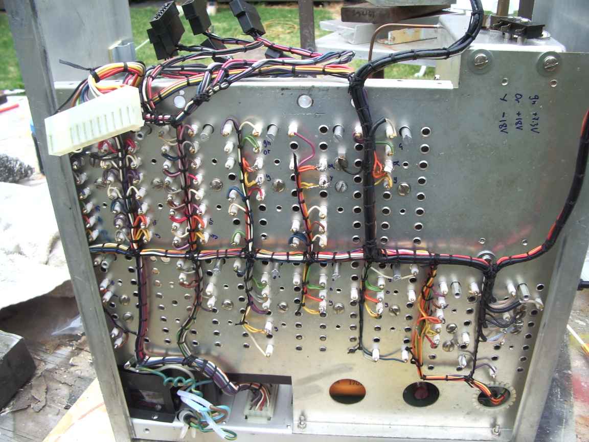
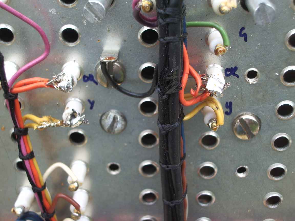
| First Fault You will find that the +/- 18Volt supply rails are at zero volts. This is due to numerous tantalum capacitors inside the many tins having turned into short cicuits. Finding them was the motivation for my Kelvin Probe project. The dead bug construction method has not contributed to reliability either. Wavetek did not believe in using PCBs ! It has all been done with point to point wiring, nicely done, but it must have cost them a fortune in expensive american labour. I redid the PSU with three terminal regulators. Lets face it, the designers of three terminal regulators were better designers than me ! Second fault. The power supplys did not use 3 terminal regulators, which were available when this unit was designed. Instead, they made their own regulators using the impossible to replace LM135 "indestructible" transistor. Guess what ? Third Fault. This is the one that even after all my work, will consign this unit to landfill. Lack of consistency in the manual means I cannot really debug the electronics, the manual does not describe all the tin cans, only the basic default models units. My present fault condition renders the output frequency to be only loosely related to the machines settings, but very stable ! Some Praise is also due. The circuit design is highly advanced and I believe, that when this unit worked, it displayed unprecedented low phase noise and lack of spurious output. I have also read that this unit provided a Gold standard in phase stability and low noise for its time. The circuit design is worthy of something that HP would have done but implemented correctly. Hmmmm..... The tin cans are not sealed, can be easily removed just by unscrewing the lockdown screw. It is not require to unsolder all the connectors....I was laboring ,incorrectly, under this illusion. The teflon terminal posts are actually a plug and socket ! The maintenance method was to indentify the failing tin can and return to manufacturer. Some tins were utterly and completely beyond inspection and repair due to internal progressive assembly. Utter and complete condemation. see my epilogue below. IC sockets in a place that is totally and utterly beyond reach and repair. IC sockets should never ever be used for production equipment, only for test and development and eproms. |
