A Phase Locked Loop based signal generator for LH through to low VHF
A most unsuccessful project.
How not to design a PLL.
This
project like far too many of the things I bite off, could not be
chewed. I wanted a phase locked loop controlled signal generator. It
was to have a rotary encoder for programming, a controlled output from
10kHz to 60Mhz. Frequency to be controlled in 100Hz steps and a digital
display whose readout was calibrated to directly read out the
frequency. Use of MECL for the high speed logic would guarantee success!
The principal of operation.
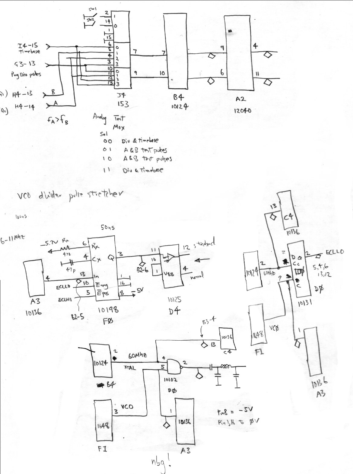
A
fixed frequency down counter generates a fixed phase reference clock.
The refererance clock was to be 100Hz. (big mistake) A rotary
shaft encoder generates two out-of-phase pulse trains, and a bit of
sequential logic figures out the direction and provides an up cound and
a down count train suitable of 74192 programmable decade counters.
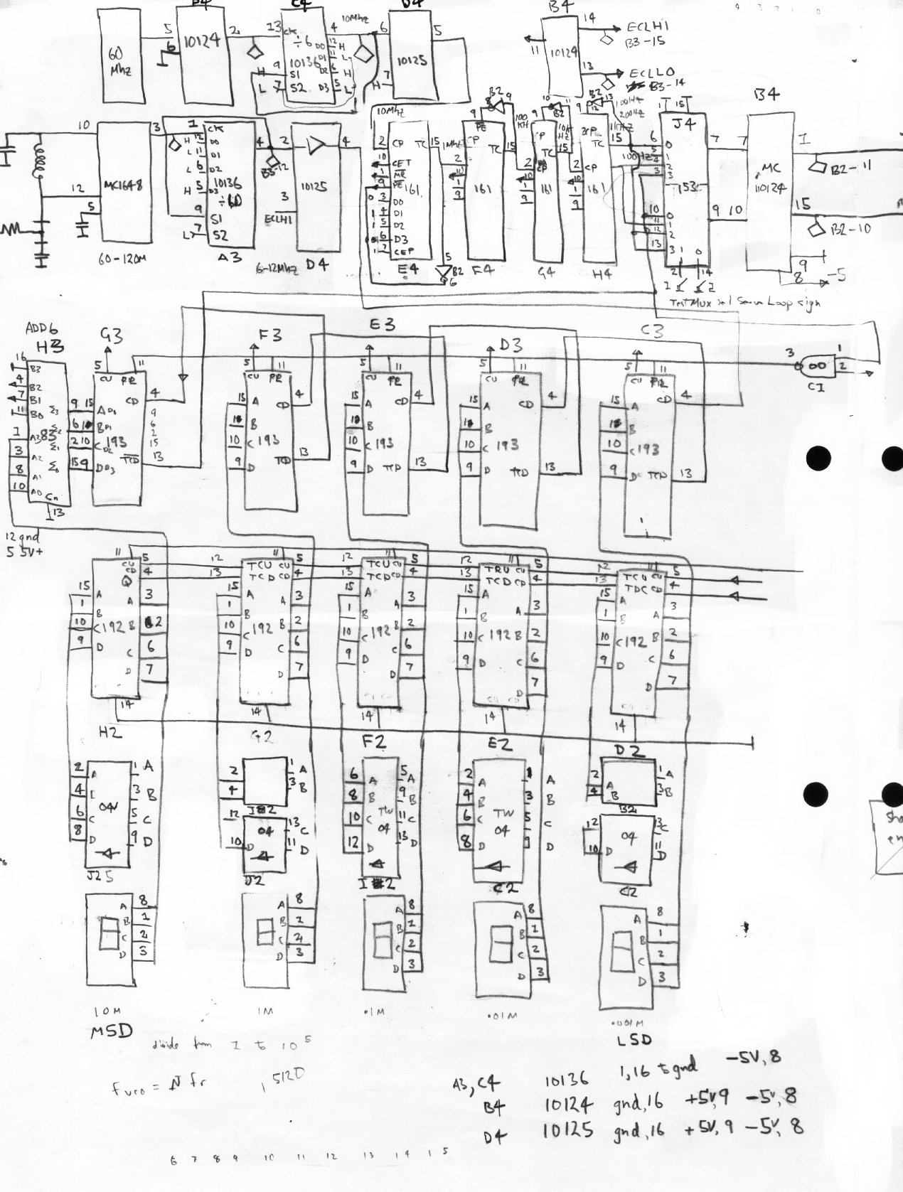
The output of this counter is added with binary 4 bit adders to
generate the calibration offset. The output of the decade counters
(with offset) is used to set the divider down count for the
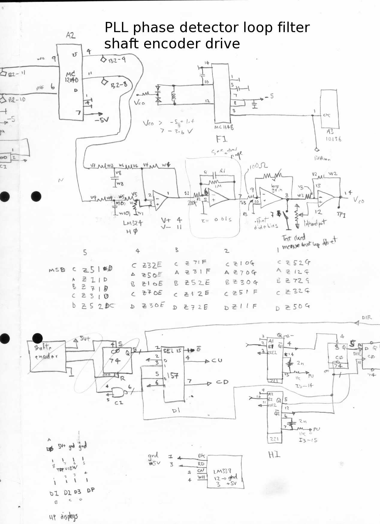
programmable vco divider. The output of this programmable down counter
is compared with the phase referance clock with an MC12040 ECL phase
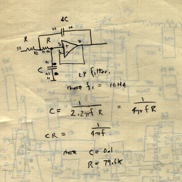
comparator. The phase comparator output feeds an integrating
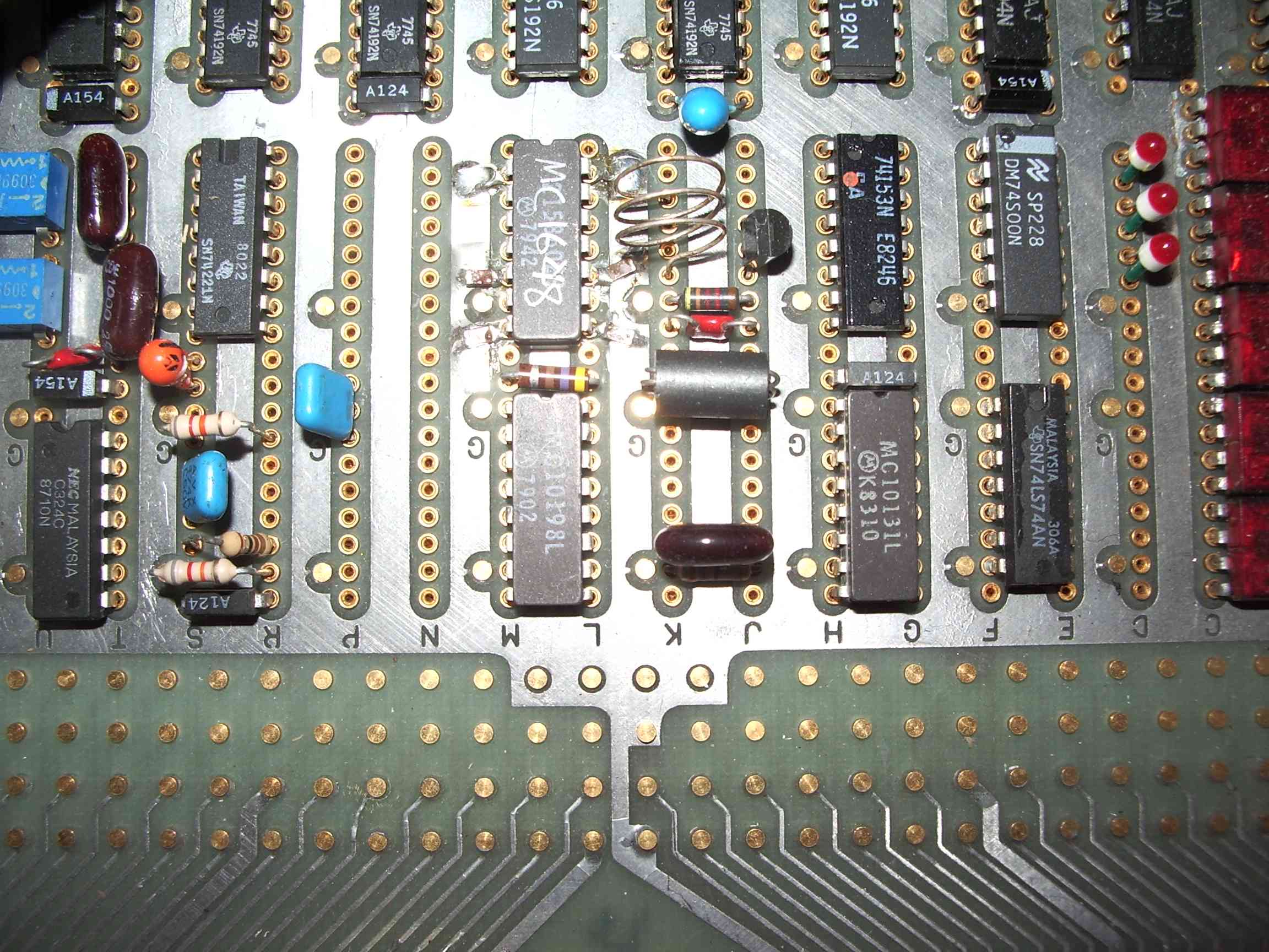
first order filter which controls an MC1648 MECL3 VCO which
runs at VHF. The output of this VHF oscillator was to feed a
mixer to be downconverted to the intended HF tuning range. A VHF
oscillator was chosen because the entire tuning range could be achieved
without band switching. At this point, more experienced engineers
will realise that what I was attempting was impossible in
practice, no matter how appealing the simple PLL block diagram model at first appears to be.
What I got for my trouble.
I got a very stable ,fully programmable, broadband random noise source!
Funnily
enough, occasionally the loop would actually lock up and the vco output
would have a half power line width of about a megahertz, not much point
then in having 100Hz increments!
What went wrong.
- The
shaft encoder and programmable divider mechanism worked flawlessly. The
intended frequency could be rapidly spun up on the shaft control and 7
segment displays showed the intended result so far , so good.
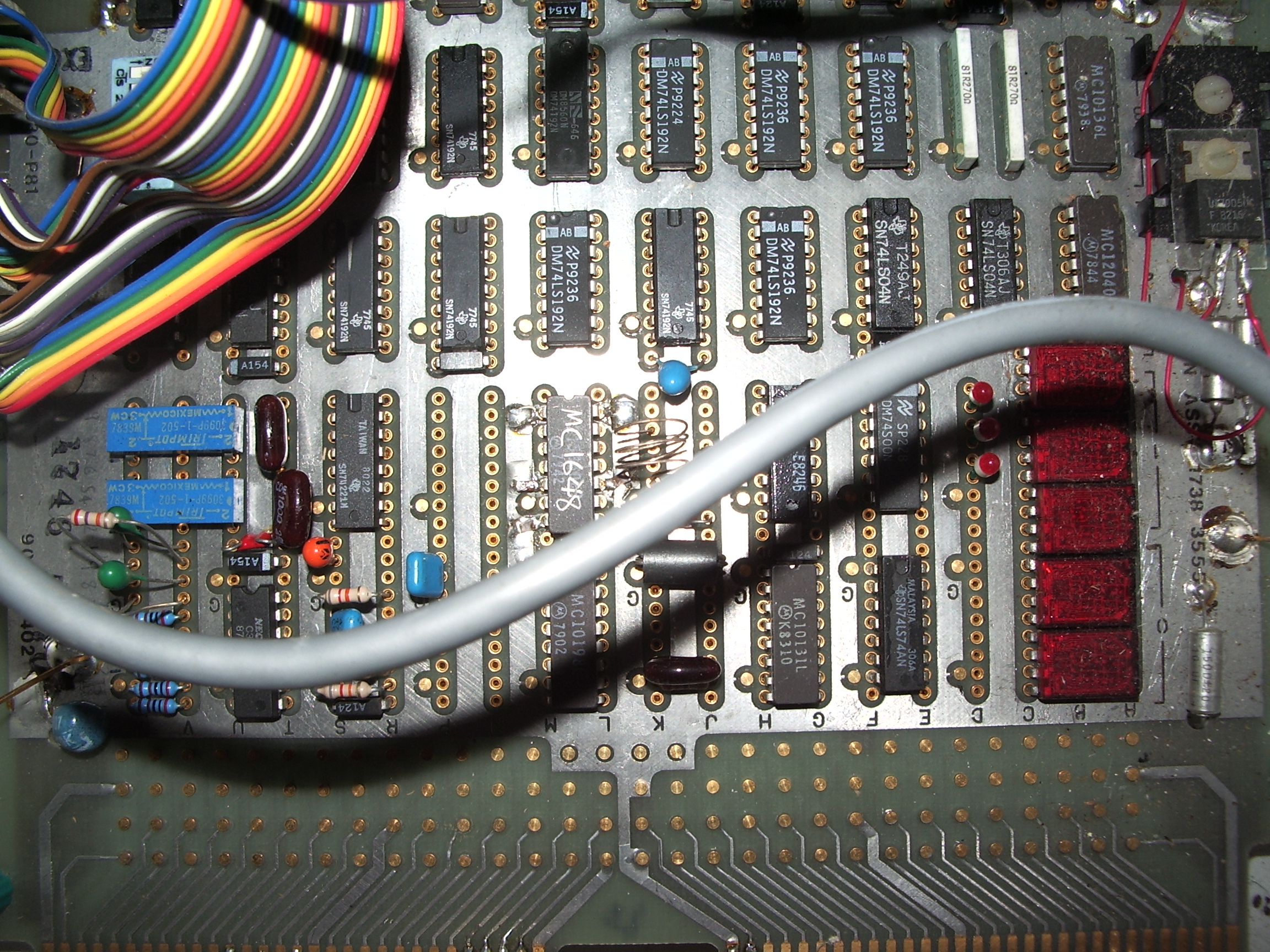
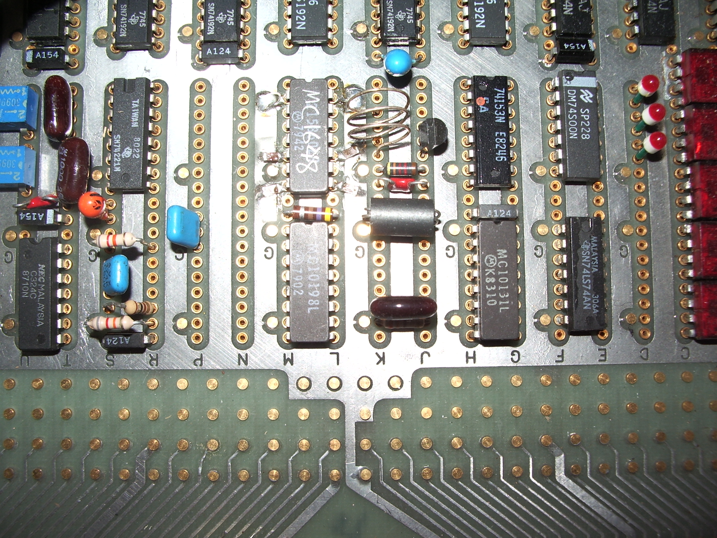
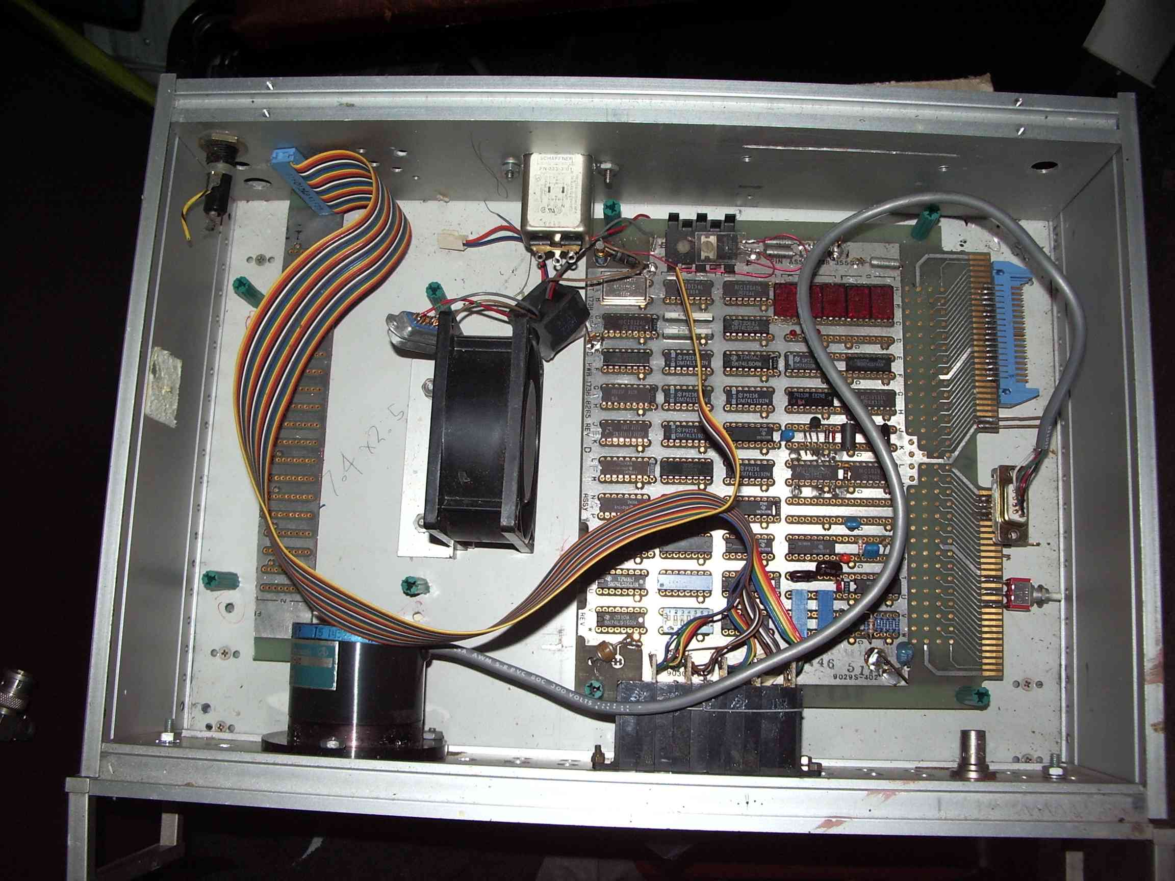
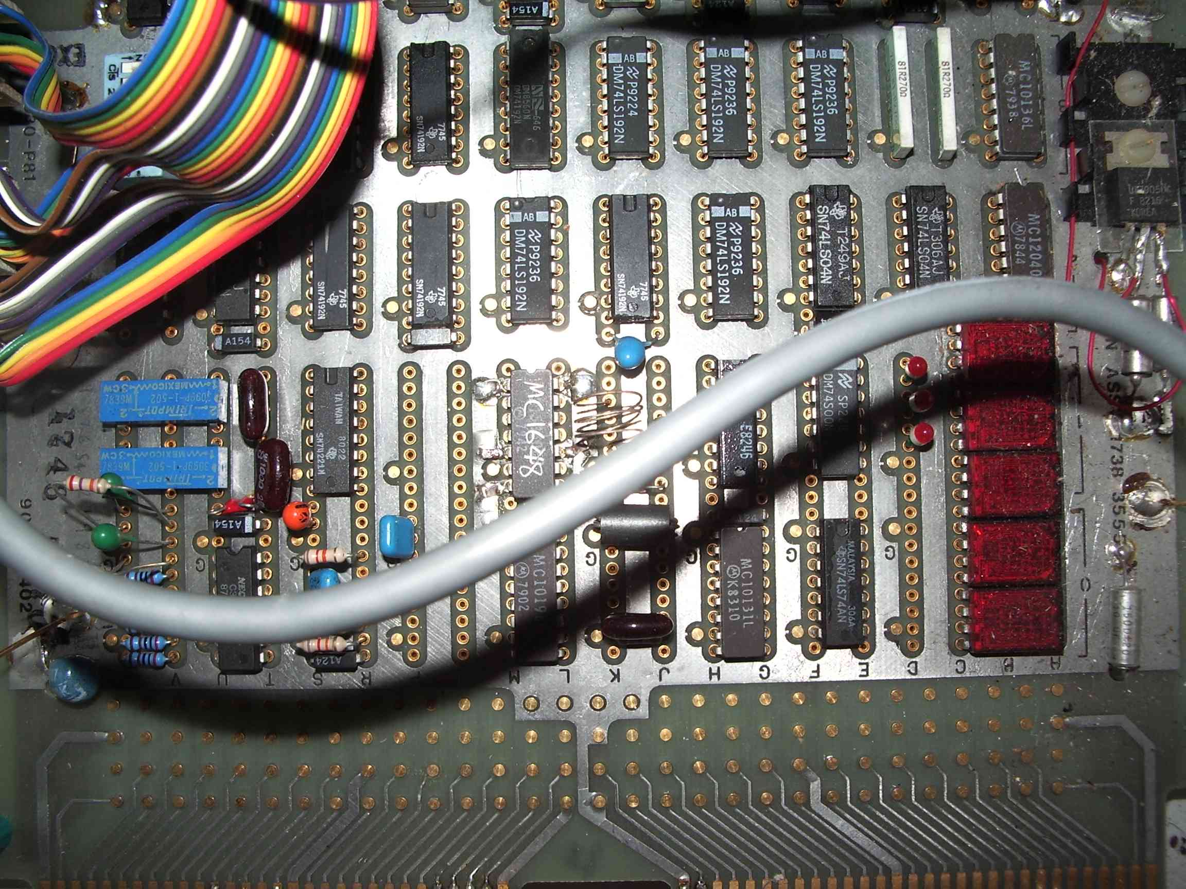
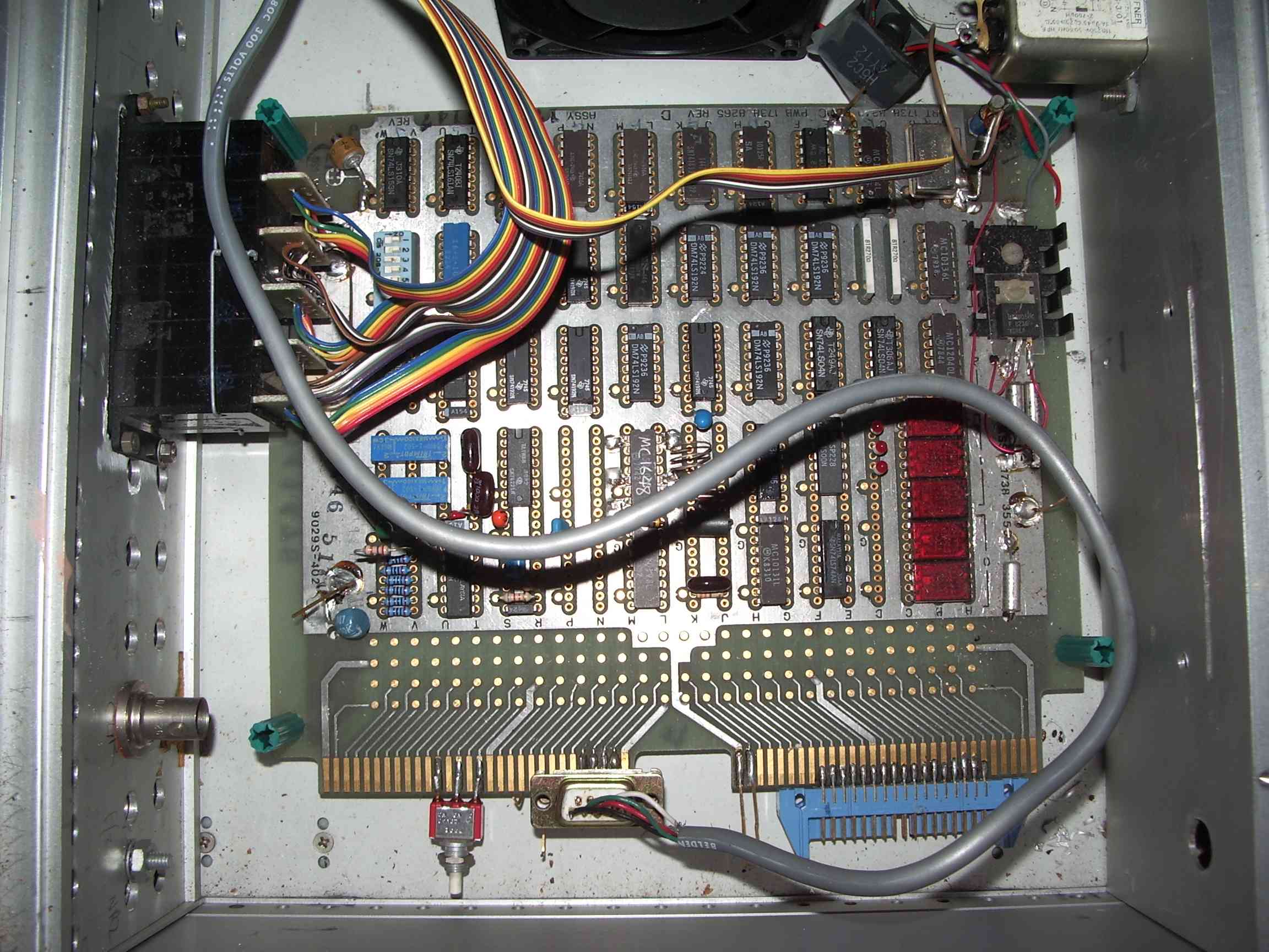
- The
VCO was mounted , unsheilded on the same wiring board as the rest of
the digital electronics. That would never work. The reason is
that an oscillator, due to its positive (regenerative) feedback is at a
small part of the cycle an amplifier of extremely high gain (compare
with an old fashioned regenerative radio). It picks up all the
nearby radiated broadband noise of the nearby digital logic and
amplifies it! The noise will impart a significant random phase
shift in the VCO, and that translates into a broad frequency spectrum.
The loop may never lock under these conditions.
- The phase
comparator filter and integrator was mounted on the same wiring board.
This part of the circuit deals with voltage magnitudes whereby
sub millivolt signals directly phase modulate the vco. The amplifiers
were picking up adjacent noise and feeding the vco with it along with
the intended phase comparator output. One would think that the phase
comparator output would swamp the noise, but such is not the case. The
VCO control voltage must be as free of spurious signals as the
state of the art permits, and such was not the case here.
- The
reference frequency was only 10Hz. That would never work! It might
work, if all the analog conditions had been met, but the lockup time
would have been huge. Any phase error would be effectively
multiplied by the loop division ratio up to VHF. The minimum
comparison frequency really should be at least 1kHz, that way loop
filters are easier to realise with practical components and the
shielding and noise requirements are less stringent.
- The
first vco divider is a fixed ratio divide by 10 prescaler. It was an
ECL MC10136 counter, it should have been programmed by the control
counter, and had I understood it at the time it should have done pulse
swallowing.
- The loop filter needed to be properly designed. I
had used trimpots rather than do the design homework. It is impossible
to set the loop parameters this way, believe me.
Is this project salvageable ?
I think not, certainly not in its current form.
However,
if an infinite amount of time was to be available then, the first VCO
divider would be part of the programmed chain, not a fixed modulus
prescaler. The MC10136 is just barely capable of this. This would
enable the reference clock to be 100Hz instead of 10Hz. There is half a
chance a 100Hz clock could actually lock up! Maybe 100Hz steps
was too ambitious. One kilohertz steps is definately realiseable with
some compromise, provided the low signal analog circuits were
completely and correctly engineered. I really liked my programmable
divider and am loathe to part with it. Doing it this way relieves me of
the burden of microprocessor development and associated learning curve.
Things
to do next time. Learn HOW to design a second order loop. Use a
pic or avr microcontroller to do the tedious system data management
functions and front panel management functions. Use a pulse
swallowing prescaler. Analog electronics get their very own die cast
box with seperate filtered power. Perhaps look at DDS synthesis after I
understand it a bit better and, this is the big if, if DDS chips become
available in Oz.
 |  |  |
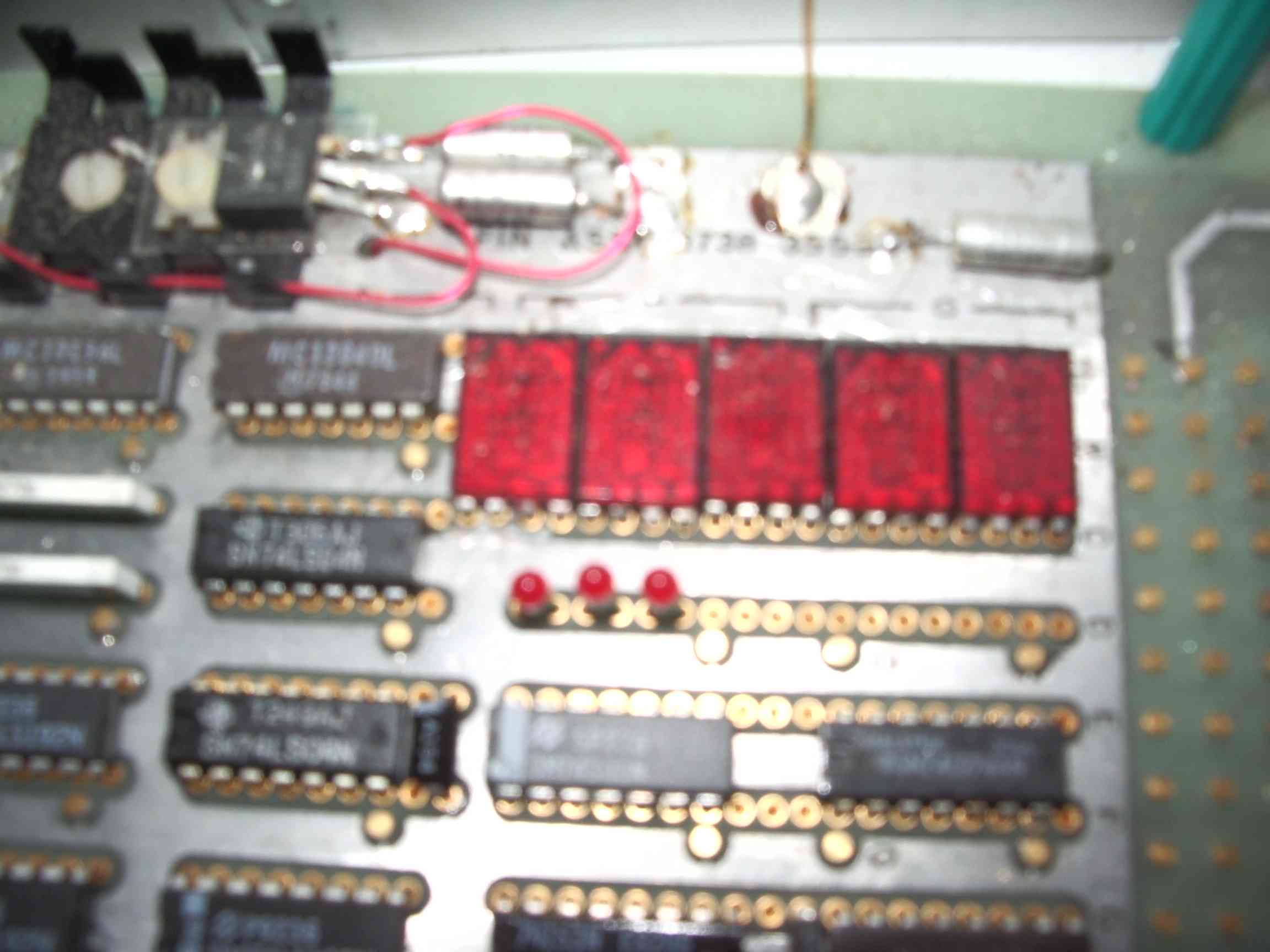
| frequency display on main board | bcd thumbwheels for direct input |
 | 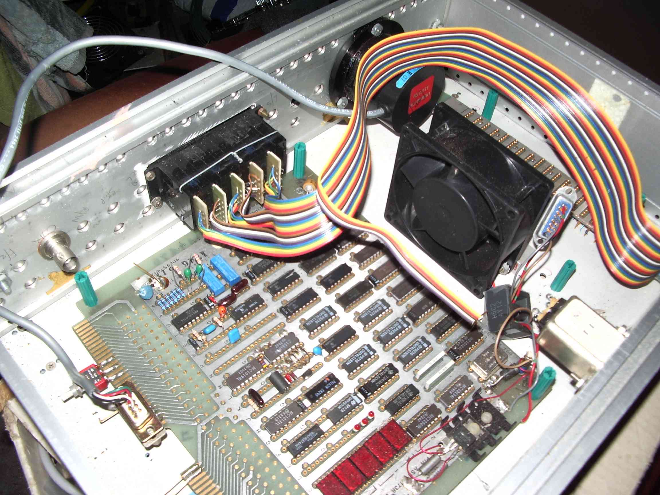 | 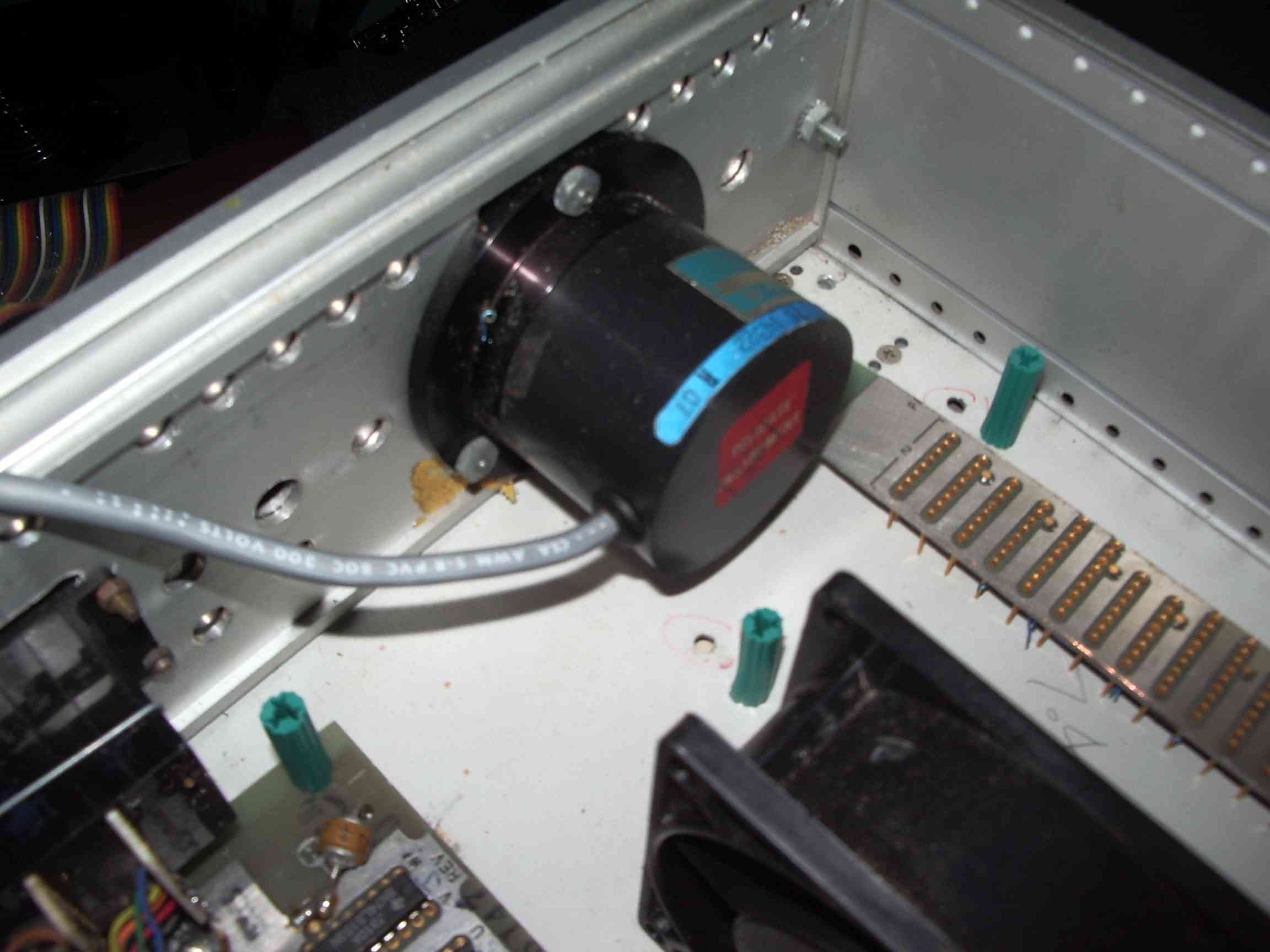 |
| major design flaw. VCO on same board | ECL gets quite hot | rotary encoder for tuning input |
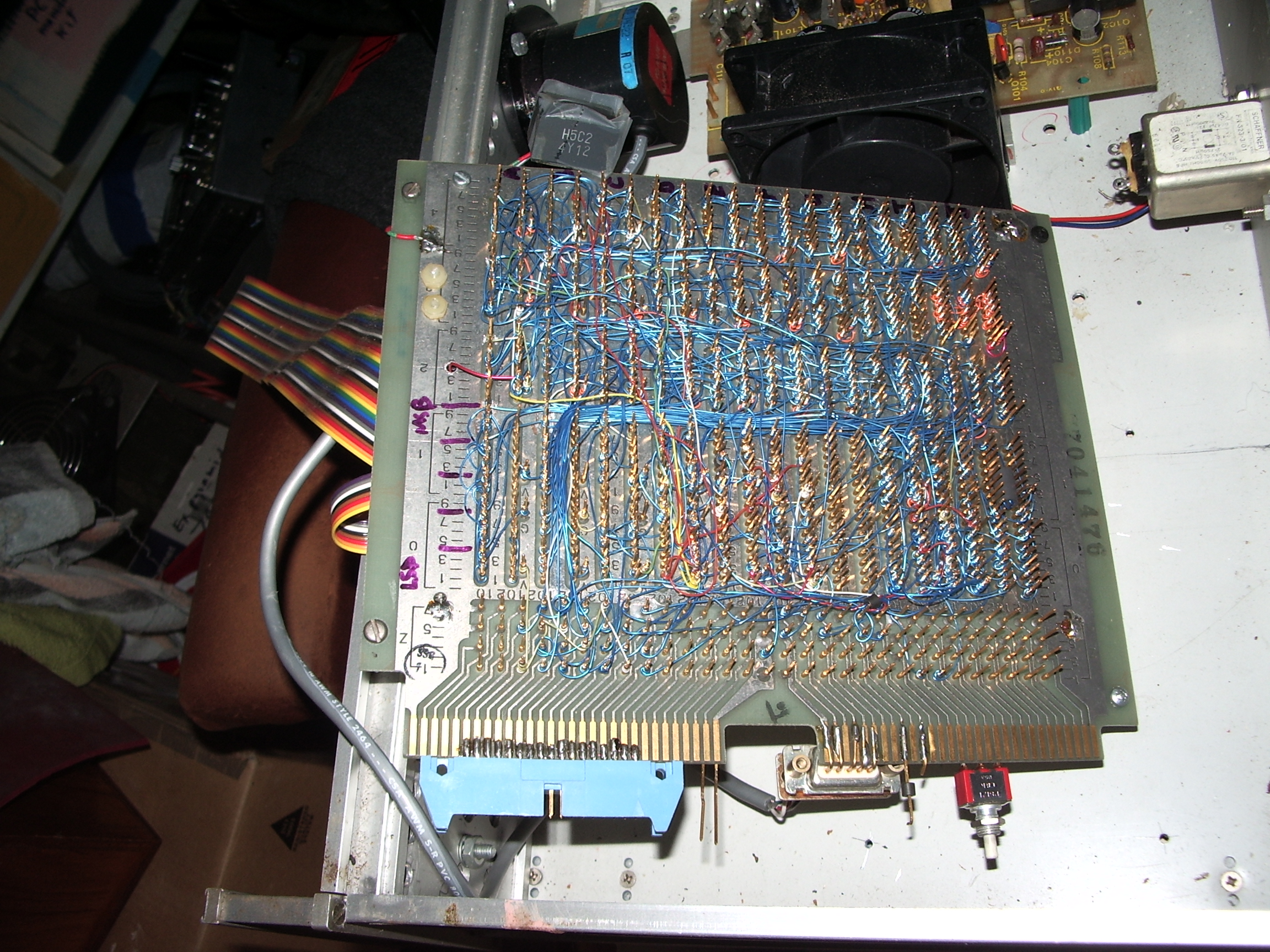
 | 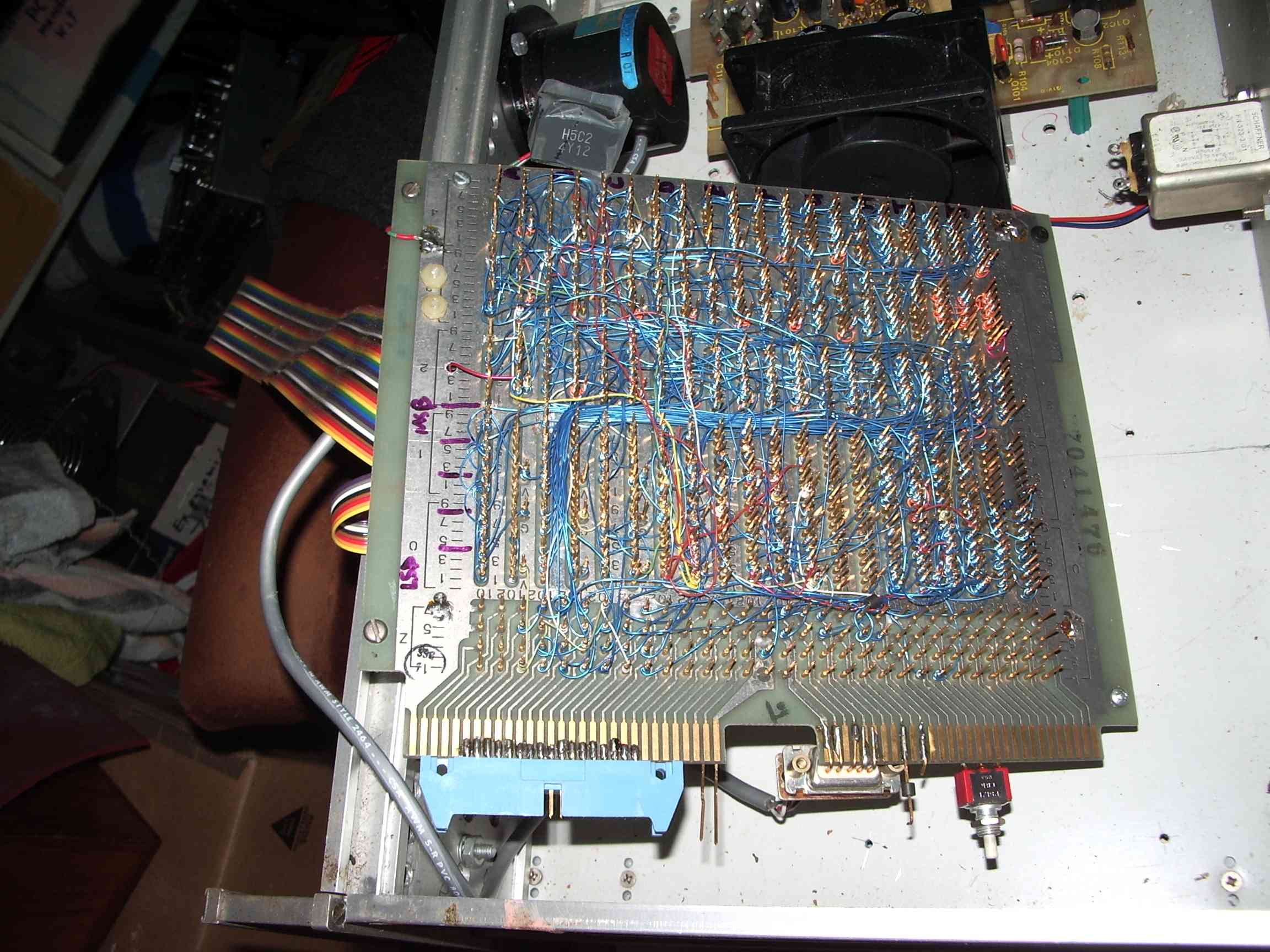 |  |
| with SMPS | wire wrap card from old mainframe | direct frequency readout |