A noise bridge is an impedance
measuring device that can measure real and imaginary components of
complex impedance at RF frequencies. It uses a radio reciever as
a detection device and a broadband noise source as the exitation source
for the bridge. This eliminates the need for a precision signal
generator notwithstanding the fact that the average signal generator
does not have sufficient output amplitude to excite and bridge and
simple detector. A radio reciever is an excellent detector being
sensitive down to microvolt signals and low bandwidth. The noise
bridge is an excellent antenna tuning instrument because it gives a
rapid and precision measurement and also the noise power induced into
the antenna is very small and will not cause interference to others.
This is my implementation of the noise bridge discussion presented in the August 1989 issue of QST. (ARRL)
It is an excellent design that by its nature can be readily reproduced.
The article has a very thorough and complete adjustment and calibration
procedure. I have not seen this article reproduced anywhere else,
which is a real pity. No exotic or hard to get components are
required.
|
 |
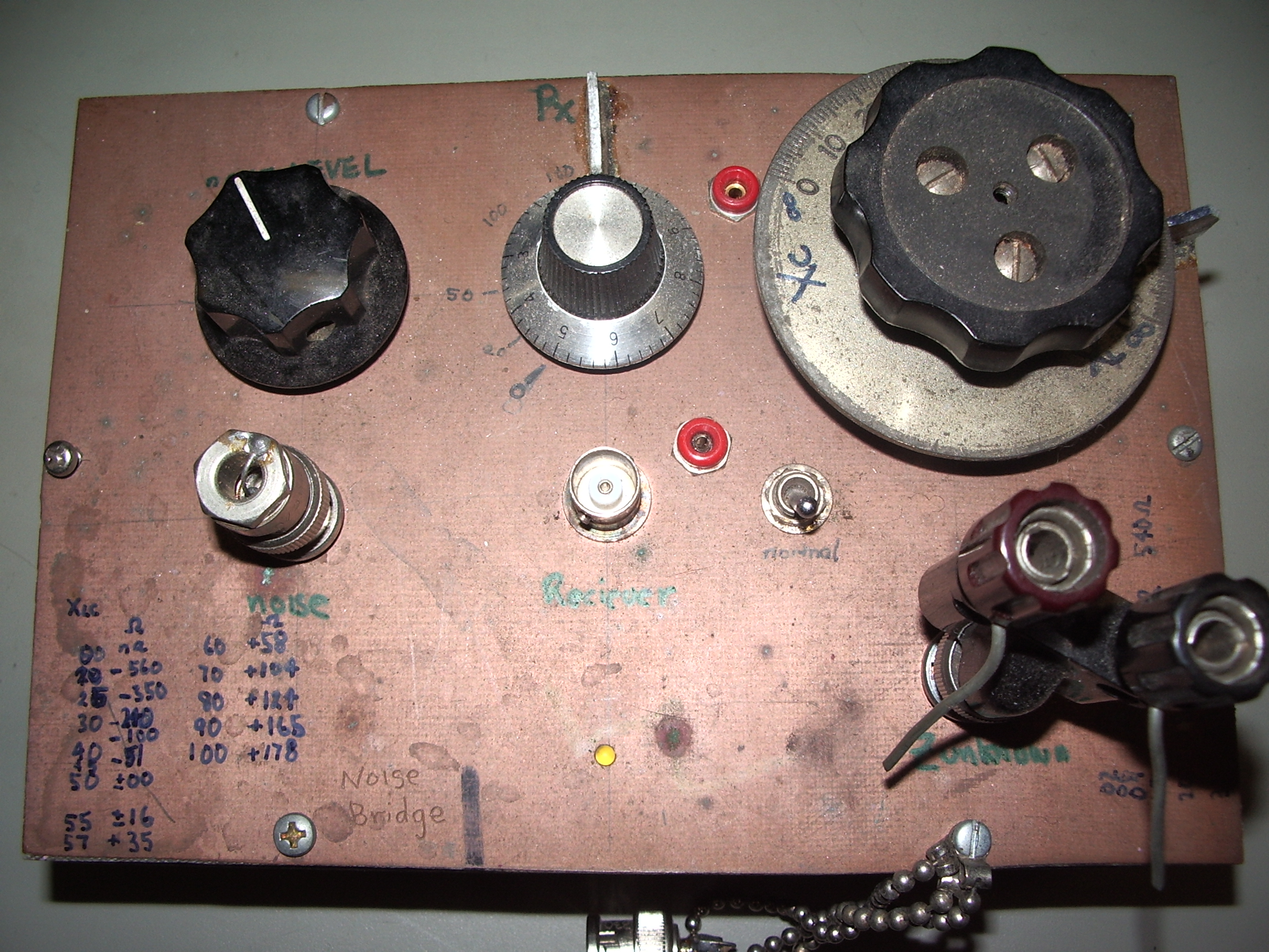
My implementation of the Impedance bridge complete with test impedances
|
 |
 |
Double sided copper clad board would just about have to be a most usefull thing since ... well it is the sliced bread of ham radio!
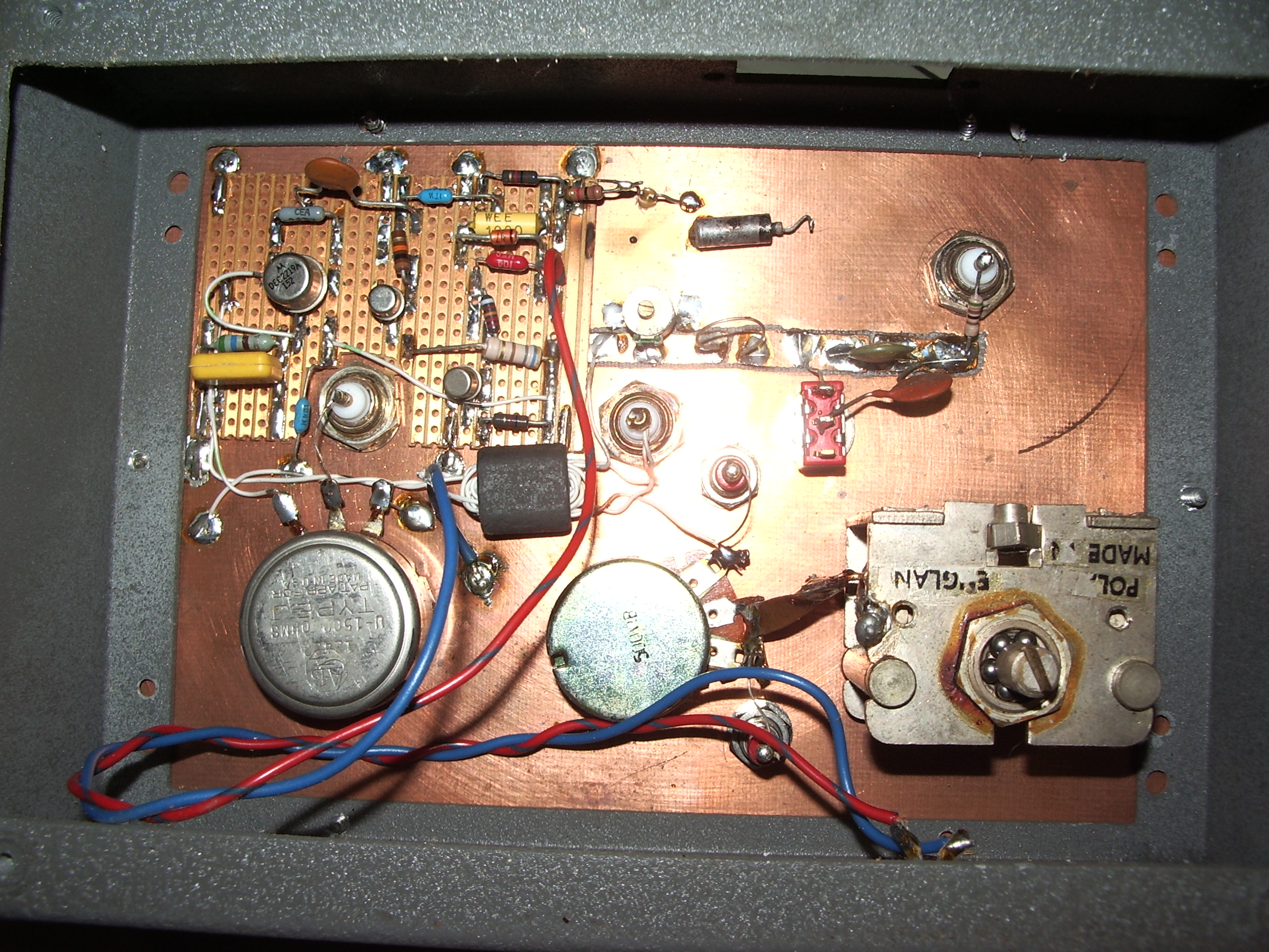
The little veroboard contains a zener diode noise source and a three
transistor broad band amplifier. I have brought out the noise
power through a seperate jack, it makes an excellent tool for testing
radios. Cost of this little project , nil. The calibration
is described in the original article. You must make the "reference"
impedance, it is just a few meters of coax but must be done right in
order to get meaningfull reactive impedance measurements. On the main
pcb you can see the one turn coil to balance the stray inductance of
the variable resistor and a capacitive trimmer to balance the stray
capacitance in the measurement arm. The adjustment and alignment procedure is given in the original ARRL article.
|
 |
| some things to note: any modern RF transistors can be used here. Use a slightly higher powered transistor for the emitter follower buffer amplifier. Any low voltage zener, below 4.7volts, will make the best broadband noise source. Use a good quality variable capacitor for the REACTANCE control and carbon variable resistor. If you can get them, use a silver plated BNC connector for the UNKNOWN terminal, it does make a differance ! The dimensions of the hairpin inductor is not really critical but make it about the same size as the pot and it will be mostly right on. The original artcile called for a 150 ohm pot, 1500 is what I had on hand and it works just fine. You must make some test impedances to get confidence in your calibrations, put some assorted metal film resistors into a BNC shell. I made a couple of them with 0,10,50,75,100 and 470 ohms to provide known reference marks on the resistance scale. Reference reactances are best made with known lengths of shorted transmission lines; various lengths of 50Ohm coax is the way to go. The bridge bandwidth is limited by layout symmetry, stray reactances and limitations in the broadband ferrite transformer. A high permeability ferrite binocular core gave a usefull performance from 1.8Mhz to 30Mhz. You might stretch the freindship to 50Mhz, but use a 100ohm pot here. |
Using a noise bridge for doing usefull stuff
quickly evaluate surplus and unidentified toroid cores for possible RF use using a noise bridge.
The one thing that I have found this noise bridge most usefull for is to quickly evaluate unknown ferrite toroids and are available for nothing inside junked equipment or as umarked grab bags in surplus stores. Most ferrite toriods thus obtained are designed for common mode RF suppression, a transformer or inductor made from these will still "transform" and "induct" but only below 1Mhz, they are absolutely useless for anything above 1Mhz .
A toroid for ham use should still have reasoneable Q at 10Mhz. Wind about 10 turns of any wire through the toroid and measure its equivalent resistance. Quickly try to get a null on the reactive arm and then null the bridge on the resistive reading. The resistive reading is the same as would be experienced by either your resonant circuit or transformer. It is interesting to sweep higher in frequency to watch the equivalent resistance go higher and higher as the core loss increases. No air core inductor has a Q as bad as a ferrite toroid. The only reason that they feature so much in the ham radio literature is because they are compact, I would even consider ferrite toroid inductors to not be all that reproducible either. (Tightly specified cores like the Amidon range are excellent but expensive or unobtainable here in Oz)
I have seen the whistle being blown in an Indian amatuer radio journal. They wound toroidal coils on a washer made from plastic sheet. Such a toroid has all the advantages of self sheilding, and absolutely no core loss, inherently higher Q for tuned circuits and they are completely reproducible , unlike the inductors wound on proprietery ferrite toroids. Furthermore the inductance may be readily calculated from formulea having only geometrical input parameters. However , such an air core wound torioidal inductor would not perform as well in broadband "balun" transformer service. It still annoys me to see in a magazine article to see constructions details that just specify the number of turns on a Blah type blah-blah core. I want to know the inductance ! I generally speaking cannot, or will not source a Blah type blah-blah core.
Another profoundly effective test to see if your junk toroid can be used as a broadband transmission line transformer, wind a quick bifilar winding of about 7 turns and terminate the balanced port with a 200 ohm resistor. You should measure 50 ohms real impedance with the reactive component near zero. If the toroid is not suitable the impedance transformation does not occur and you get strange non integer ratios or nonsence readings or significant reactive impedance.
The real suprise is to examine a couple of ferrite beads. Some are amazing, just threaded over a piece of wire ( one turn coil) comes up at 30Mhz as 40 ohms resistive! and you wonder what force of nature can turn a one inch piece of wire into a high resistance!
| My junk box toroids seem to fall into these classes. | |||
| class 1 | Useless above 1Mhz | only good for rf supression, useless for anything else | green,shiny jet black |
| class 2 | Useless above 4 to 5 Mhz | good for rf suppression, some use as transmission line TX , switchmode PSU inductors | yellow, white,matte-black |
| class 3 | "High" Q at 10Mhz | good for transmission line TX, some use possible as tuned circuits (Q and L must be tested at the desired operation frequency) | red, yellow |
The Q of the tuned circuit can be directly measured on the radio by tuning for the 3dB down points.
If the half power points are close to each other then that inductor would be usefull as a tuned element. If the peak is broad then the Q is low, the core could still be usefull as a transmission line transformer.
I have found that, at least in my junk box, the class3 toroids are rare. You can find these on old computer motherboard where they are used as step down buck regulators, they make good rf inductors up to 20Mhz. Sometimes they are used by mistake for RF supression , if which case they are not very effective! Discarded computer PSUs are another possible source.
Sometimes the surplus grab bag toroids are colored. Bare black cores are nearly allways intended for rf supression and useless above 1Mhz. Red cores seem to be ok for RF, Green cores are for RF supression and are otherwise useless. Yellow cores are ambiguous, they seem to be either good for RF or just for suppression service. Allways check a mystery core before use with the noise bridge to avoid frustration. Its a pity that core manufactures never agreed to an industry standard core color code that indicated permeability and some frequency/ core loss metric.
see also my simplest but most accurate Inductance measuring tool.

home
Tue May 13 19:08:30 EST 2008
added content, copyright notice,formatting
Tue Dec 21 18:53:12 EST 2010
added complete schematic, formatting