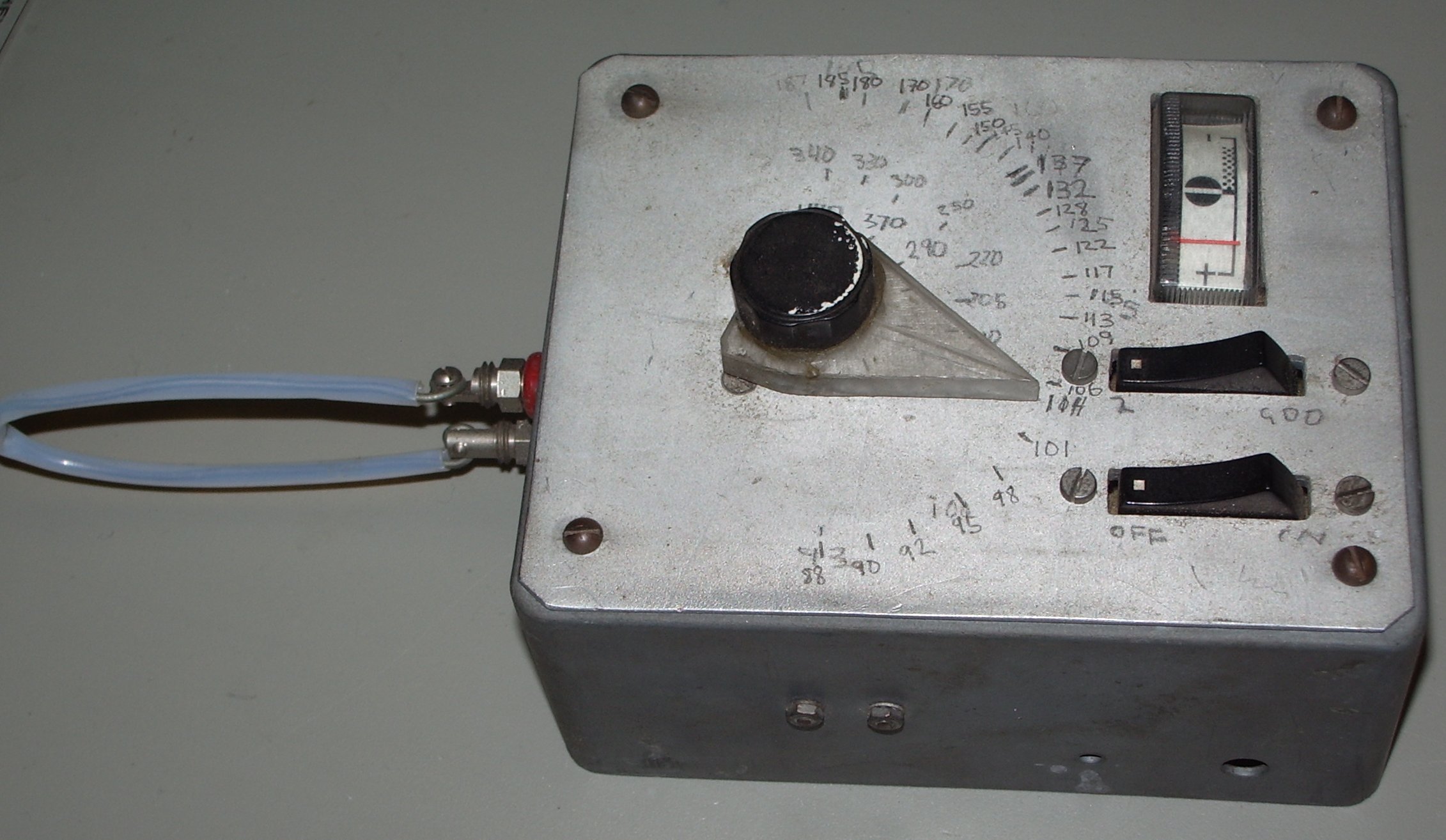
A Grid Dip Oscillator
constructed in 1984
based on a balanced push-pull FET oscillator
based on a design first published by the RSGB in the RSGB VHF/UHF Manual
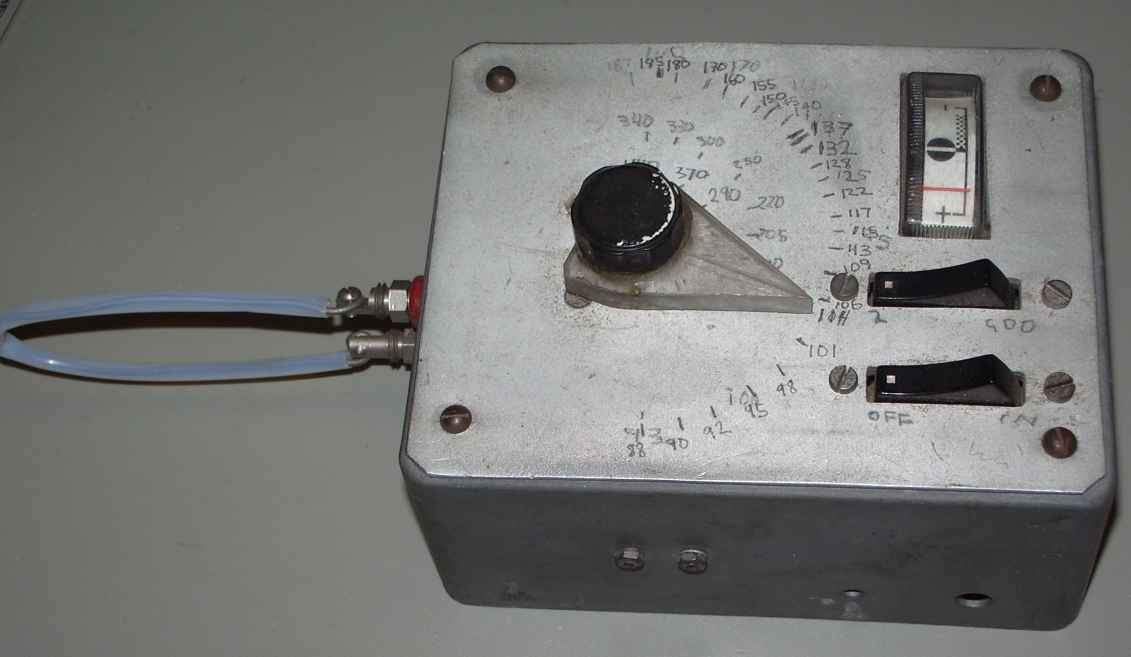
This
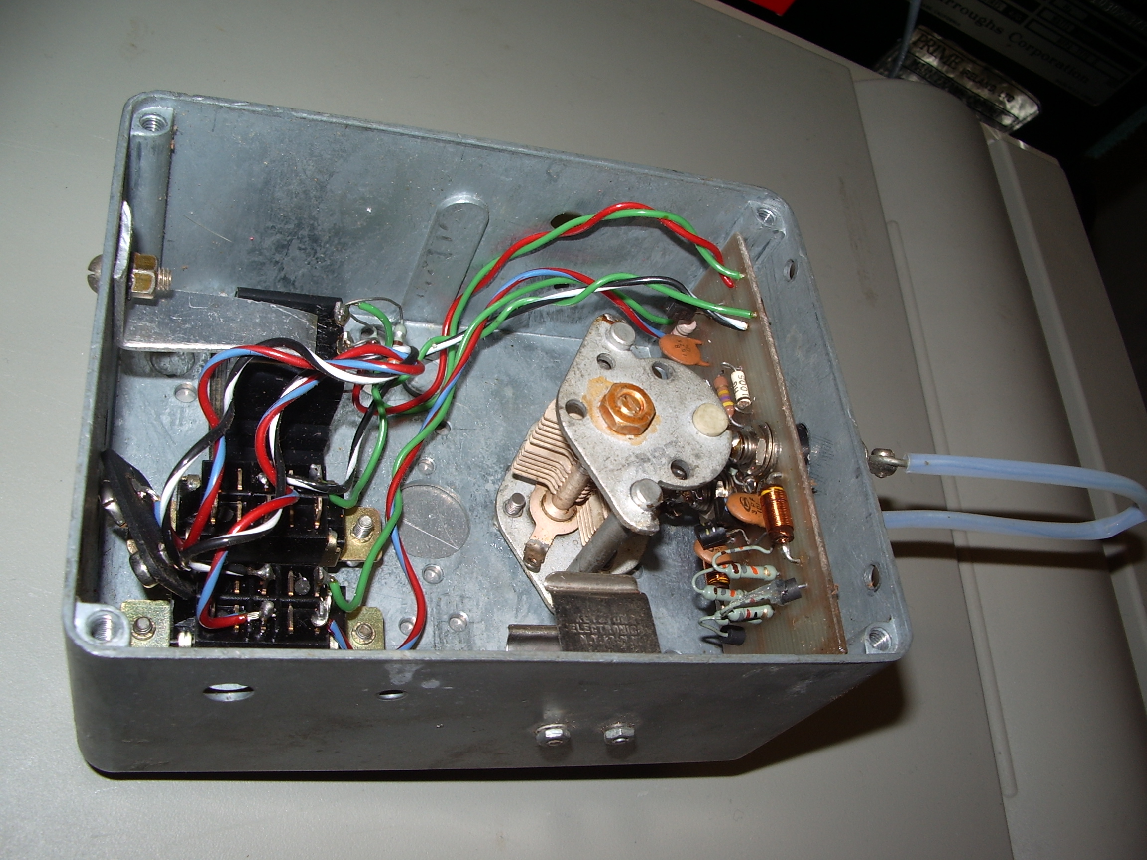
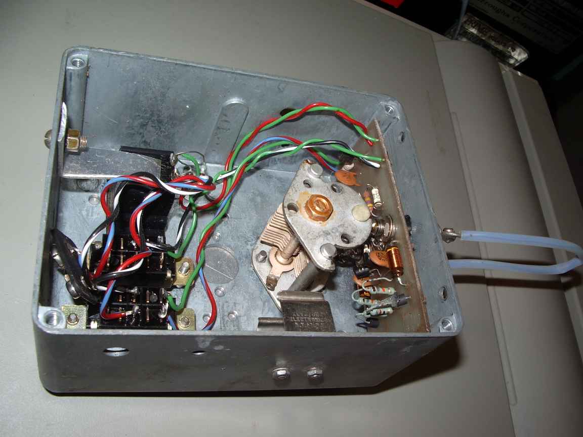
Grid Dip Oscillator is biult directly into an old die case box.
The coils which consist of nothing more than assorted hairpin
inductors are mounted on banana plugs or for the UHF "coil" is nothing
more than a bent piece of 1/8th brass brazing rod jammed into the
banana plug receptacles.
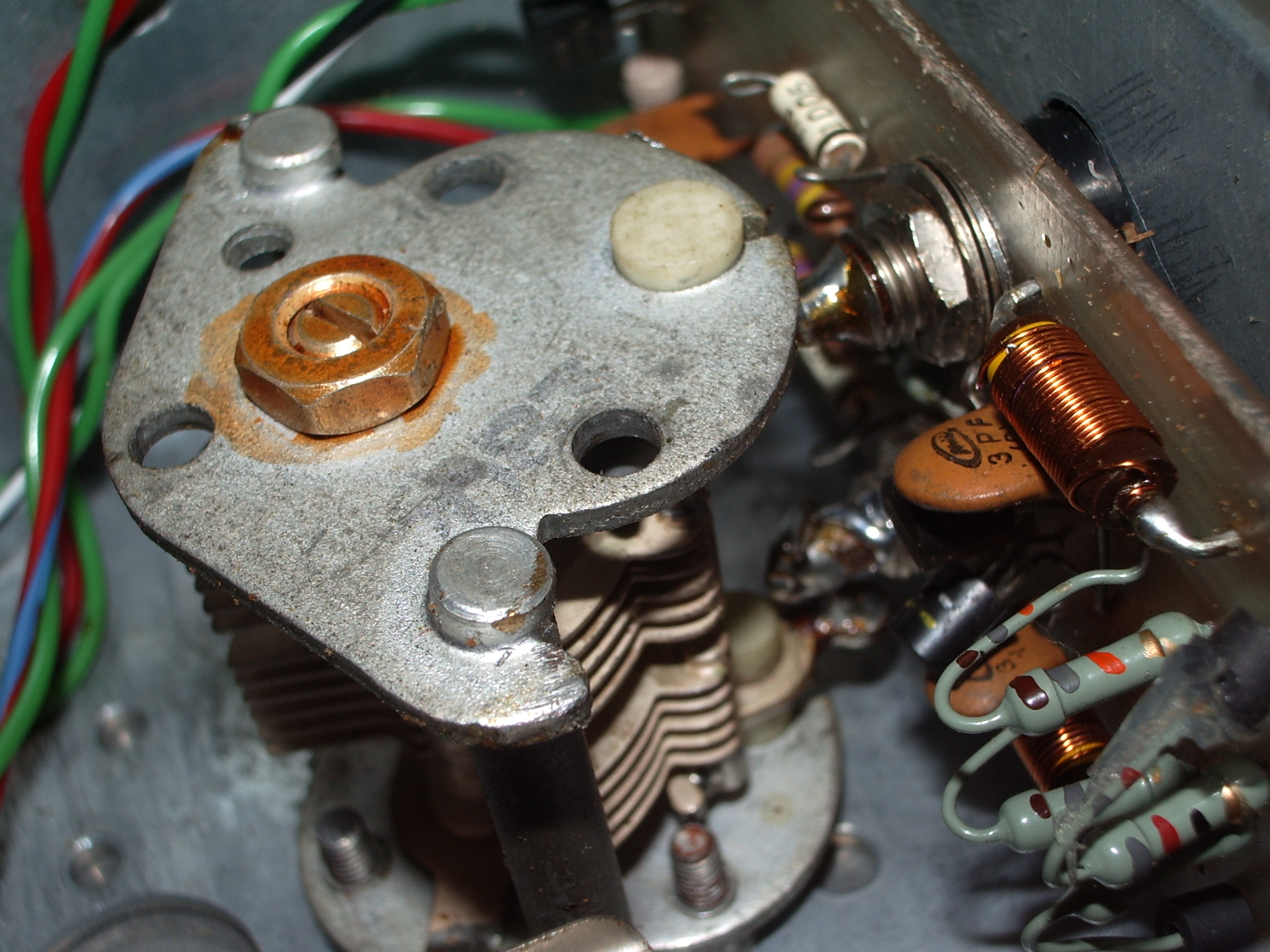
The little PCB carrying the oscillator
is directly mounted on the banana plug receptacles so as to minimise
every possible source of parasitic inductance.
Choice of FETS
is quite critical to the performance of the unit. I used MPF102s which
was a marginal choice. A proper UHF rated FET would have worked better.
The feedback capacitors need some attention. Too little feedback
will result in poor performance at the the low frequencies. The
benefit of a balanced oscillator is that the resonant circuit
needs no inductive of capacitive taps, there are very few
spurious responses across the span of the variable capacitor which is
an inevitable consquence of an unbalanced oscillator.
The variable
capacitor used here is completely unobtainable in this day and age and
was originally recovered from some scrapped radio equipment. It still
is possible to find this kind of capacitor at ham fests. The
capacitor should not have a maximum capacitance greater than 50pF or
UHF operation will be ineffective.
The maximum frequency of this GDO was about 470Mhz. It could have been higher with a better thought out PCB layout.
The
balanced oscillator was very successfull with a very nice smooth
operation and consistent performance. The next GDO project for HF will
be based on it again.
 |  |  |
| the banana jack to pcb trace junction needs more thought to minimise parasitic inductance | |
include circuit here