The AC Ammeter
the Next Generation AC Ammeter
by Ralph Klimek 2006
keywords:
AC
Ammeter, self calibrating, inherently linear meter scale, self powered,
simple resistive shunt, no active electronics required.
It
is a commonly encountered problem that the technician engineer wants to
monitor directly the AC current drawn by a mains powered appliance.
There is a small assortment of traditional tools. The classical
AC ammeter is a moving iron instrument with the instrument coil either
carrying the full load current or is driven from a shunt. It is rare to
see this sort of instrument available second hand because the coil is
invariably blown by excessive current. The moving iron instrument
is the gold standard, however there is not a simple relationship
between the meter deflection and current magnitude. The meter scale is
distinctly non linear and you are forced to have faith in the meter and
its original calibration. The moving iron instrument is not self
calibrating in the sense that if you have one good data point, you can
interpolate the rest. This design meets this condition.
The alternative is the now ubquitous
hand held digital multimeter with a 10A shunt. I have little faith in
the calibration of the cheap units, most of them could not sustain 10A
continuously anyway.
I
wanted a self powered, inherently linear and self calibrating AC
Ammeter panel meter that was not a moving iron instrument because mainly
I did not want to spend the considerable sum of money for a real
instrument that would still be subject to destruction by a transient
overload.
The alternative AC ammeter solutions involve the use
of resistive shunts and measuring the sub volt ac signal with an AC
millivolt meter. This is an elegant by not straight forward.
The moving coil instrument is a DC instrument, better suited to
measuring voltages of the order of ten volts. It would need a
rectifier that adds a high level of uncertainty into the reading when
taking into accound the forward voltage drop of any real world diode
bridge.
I wanted
my AC ammeter to have a full scale deflection of 10A. If I used a
0.1ohm shunt, this would only drop one volt, and dissipate only 10W.
Thats a reasoneable amount and I certainly would not want to use
more resistance than that. A one ohm shunt would dissipate
100Watts at 10A and that is just silly.
The 1 volt
developed across a 0.1ohm shunt is not enough to drive a diode and
moving coil voltmeter without a grossly non linear meter scale.
I did not want to go to the trouble of supplying a separate DC
supply and ac amplifier, thats already getting excessively complex.
How to step up the voltage to something more measurable ? Use a
step up transformer across the shunt and use a bog standard diode
bridge to drive a simple DC voltmeter that now has, at full load, maybe
30 volts to measure, which is trivial to do. The step up
transformer is nothing more than a plug pack transformer with the low
voltage secondary used as the "primary". This steps up the
voltage nicely. Even better is the fact that the "voltage source"
driving the transformer has a 0.1ohm driving impedance, so the load
presented by the transformer and meter load is not going to influence
the reading. Even better is the fact that the meter circuit can
be grounded, it is not floating at mains potential, and this opens up
the possibility of safe remote measurement of mains current.
In
practice , this circuit when tested with a radiator as dummy load
and a large variac showed totally linear and expected
readings from 100mA to full scale deflection at 10A.

The
circuit is calibrated by monitoring the resistor shunt voltage with an
AC millivolt meter. The pot is tweaked to give the correct meter
reading. It is sensibly linear and does not exhibit the pathology
that a current transformer and moving iron instruments show. A
BNC outlet permits direct monitoring of mains potential current with a
scope. (usefully for debugging switch mode PSUs or other impulsive loads) A
modern digital voltmeter with an AC range is sufficiently sensitive to
calibrate this instrument. The only other requirement for
calibration is a known high wattage resistor or another moving iron
ammeter that you have faith in.
 | 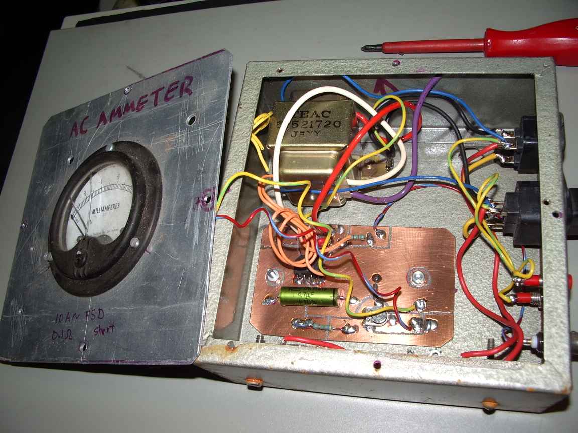 |
| test points are for initial calibration | step transformer from discarded ghetto blaster |
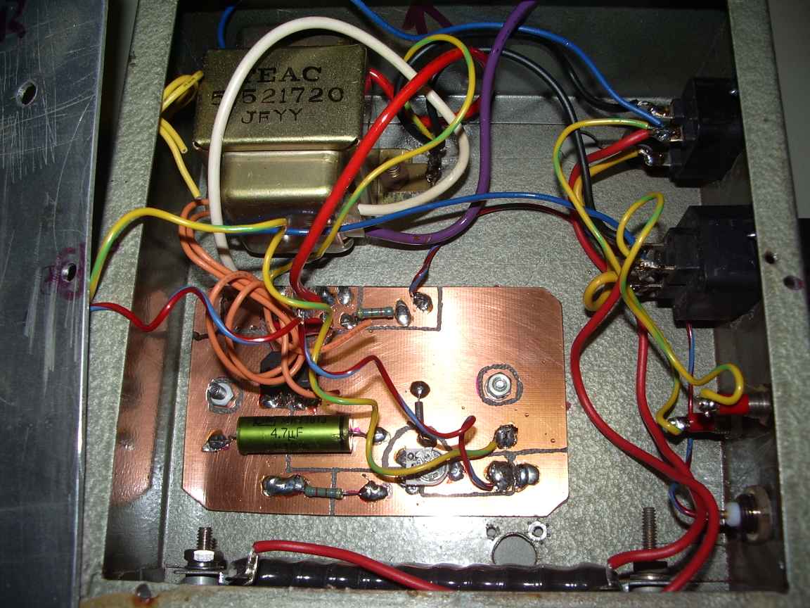 | 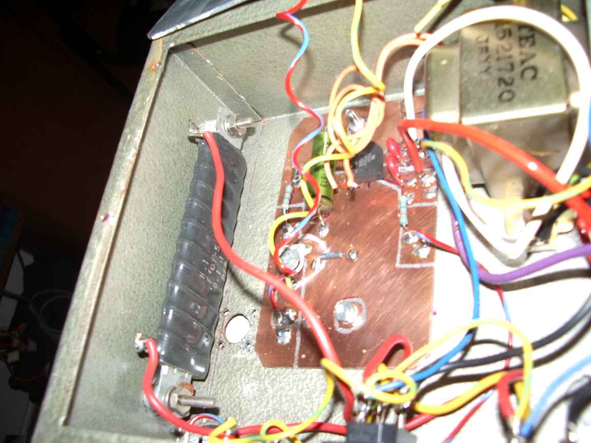 |
| a very complex circuit. filter cap is non electrolytic for long life | the 20 watt shunt resistor |
homepage
mod record;
Fri May 9 18:51:28 EST 2008,
Mon Nov 22 18:37:57 EST 2010


