The CTuL logic family.
Complementary Transistor Micro Logic by Fairchild and ITT (second source).
These data sheets are presented to those that serviced the Burroughs
and either loved or loathed this logic family. They are historic
in the sense that they are dated 1966 which is about as
pioneering as it gets. This logic predates most other logic
families allthough I believe Motorola ECL to be actually older. (Motorola published application notes dated 1962 for ECL which is amazing)
Notice that the data sheet includes
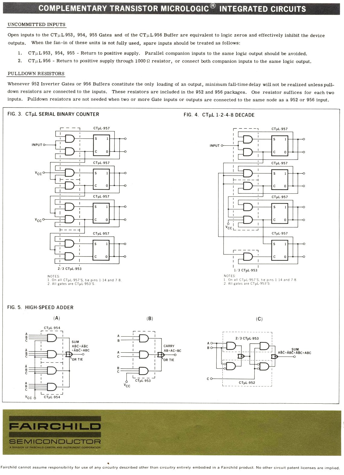
some application notes, like the design of a 4 bit counter. One day
about 10 years into the future something as complex as a 4 bit counter
or shift register or multiplexor would be put into one IC package. But
then , this is 1966. I cant imagine how much one of these simple ICs
would have cost, but given that mainframes of the day cost
millions the inference is not hard to make.
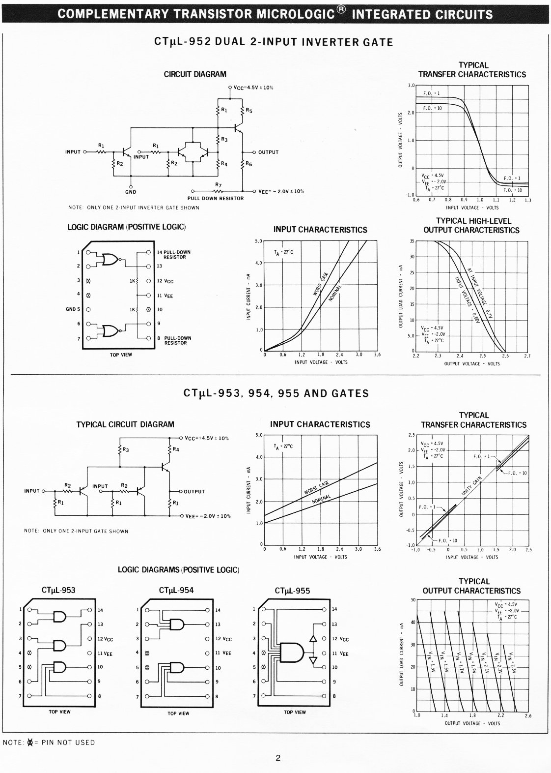
The logic family looks a bit like RTL but the output transistor
topology in RTL has a common emitter configuration which saturates to
drive a level low. This is good, this has a low output impedance. To go
high, it must drift high, being pulled up by a collector resistor load.
This must severly limit its speed as well as presenting a high
impedance to the output load. Saturating the transistor just slows it
down, this wasnt addressed in CTUL, only Motorola had the right insight
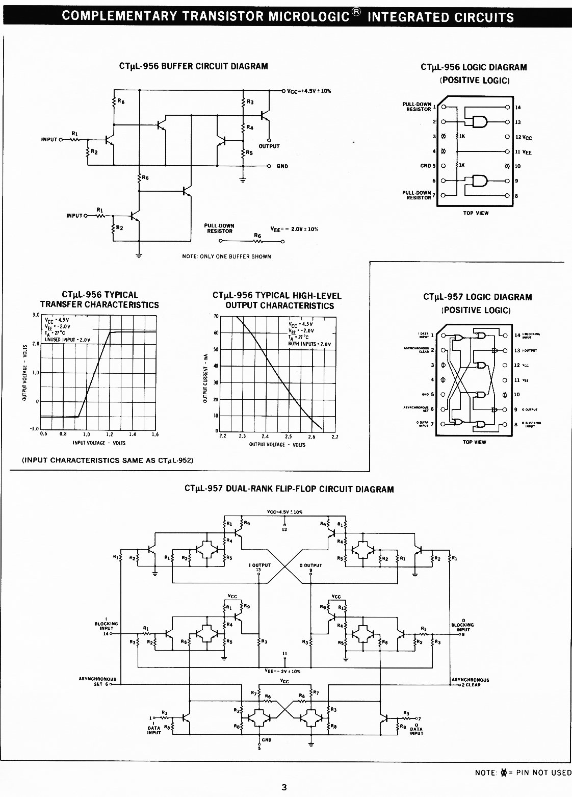
about this. CTUL , however had open emitter outputs with emitter
degeneration and this could drive low impedance loads and thus also
achieve a high fanout. This enabled CTuL to run at 8Mhz in the
Burroughs B7800 and its predecessors which was a very impressive figure
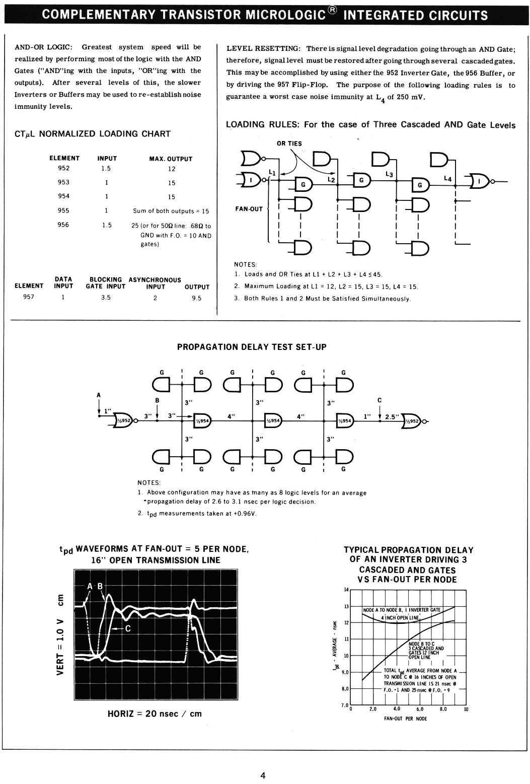
for this vintage of device. Have look at the horrible fanout rules.
Why didnt Burroughs use TTL ? Because there wasnt any. Texas Instruments had not invented it yet.
Why didnt Burroughs use ECL ? They should have, but I dont have the real answere to that, its a complete mystery. See also my ECL rant.
I wonder if this logic family was used in the Saturn V vehicle stage flight controller?...have a look at the flight manual
I dont understand the purpose of R3 and R4 and the transistor that it
provide bias for. It must be to stabilise the HI level at the open
emitter output, otherwise it provides nothing to the logic
ugh
home
Thu May 15 19:05:55 EST 2008