ARMY wireless senders C42 and C45
My partial extract of the EMER (manual) for the C45
(EMER....Electrical and Mechanical Engineering Regulations)
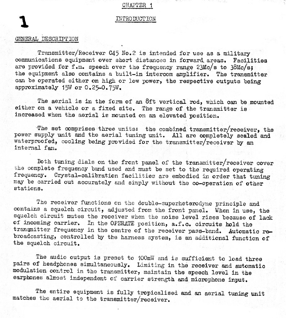
The wireless set C42 and C45 were vitually identical set covering
differant frequency ranges. The C45 cover the high HF range and
the C42 covered the low VHF range.
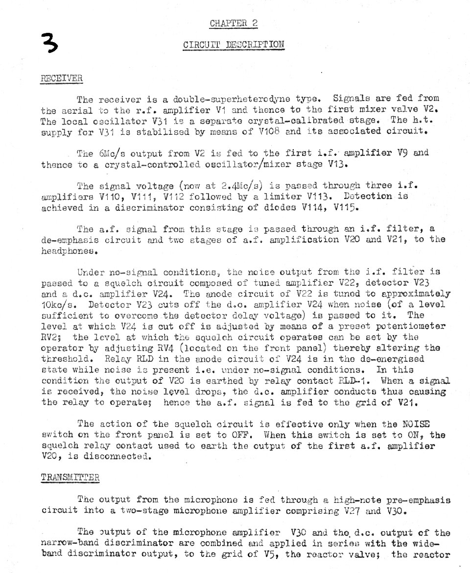
They were wideband FM transcievers with a one band wide coverage
transmitter and double converstion radio. They used differant
construction methods to the C13 radio but were still biult like the
tanks into which they were installed. They appeared in large
numbers in the surplus market from the late seventies onwards. Many
hams succeeded in getting these rigs on air, unmodified , onto 6 meters
and some onto 10 meters. At 52 Mhz the front end 6AK5 was less
then optimum noise figure and benefited from even a low cost transister
rf amp to improve noise figure. They were not really suited to
"narrow band" FM chanelised operation as they lacked the repeatability
to put the carrier into the narrow if range of converted commmercial
low band FM transcievers. However, with a counter on hand, they
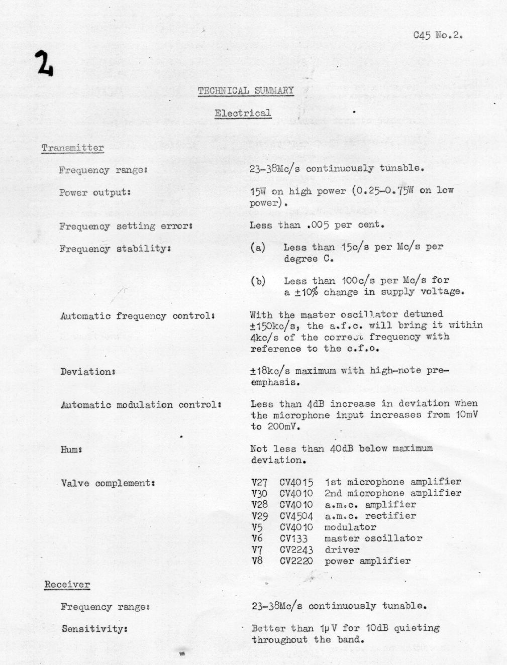
could be reliably put "on channel". The transmitter portion had
a nominal 10 watts output. My C42 would often contact via
tropospheric ducting paths between Melbourne and
assorted Queensland locations during the Xmas season when many hams
were off work. However, in the early eighties many Melbourne hams had
C42s working and CQs were allways answered on 52.525Mhz and
53.5Mhz.
I never got a manual for the C42, however a I obtained a
zillionth generation copy of part of the C45 manual which proved to be
the same circuit, for all intents and purposes with only the LC constants differant.
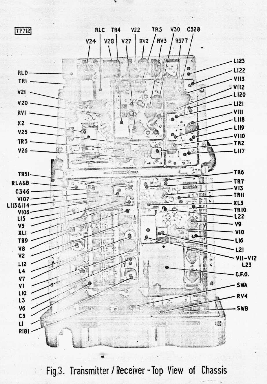
Presented here are the schematics for the C45, scribbled on the
anotated by myself, many years ago. They are 3rd generation photocopies
done about 1977 and recently "imaged enhanced" with the GIMP. My usual
advice is still , best to goto royalsignals.org and follow their
procedure for downloading the EMER manuals which are of much higher
reproduction quality.
For
those lucky hams who have the C45, they can be used on the 10 meter
band, there are even a couple of 10M repeaters in Australia, however
you would need a pair of C45s to use the repeaters due to the RX TX
frequency split.
For those wishing to restore or repair their C42 and may not be
of a sufficiently advanced vintage to understand the finer points of
vacuum tube technology , my advice , simply is this. It is
possible to repair and maintain this set with nothing more than a
multimeter and a digital frequency meter. First step, check ALL
resistors, especially screen grid droppers and anode loads, they will
have drifted too high after 50 years. Then check all screen bypass
capacitors for leakage. If a tubular capacitor says "HUNT", just
replace it. Millitary spec valves of this vintage "never" failed.
If your C42 does not quite work, it is allmost certainly NOT due
to a faulty valve! Nevertheless, check that all valve filaments
light up, and that no silvery getter material on the valve envelope has
gone white. White means the vacuum seal is broken.
A signal
generator for checking the radio is pretty much essential, however if
you live in an area with lowband television, then a piece of wire and
the set tuned to the video carrier (56Mhz) will do.
To check the transmitter, ( you should be or know a ham ) you
need
dummy load and frequency meter. Operation with other
hams on 52.525 Mhz FM calling chanel that use narrow band crystall
locked and crystal filter converted low-band FM transceivers is
possible if you keep peak deviation down and monitor your actual
transmit frequency with the frequency meter. The DFM is a must, the
film strip dial repeatability and settability is good, very good,
state of the art in 1955; but it is not good enough for the "modern"
transceiver. On air use requires the use of a low pass filter if
you need peacefull and happy non ham neighbours!
Australian hams may only use the set C42 between 52 and 54 Mhz, so sadly, no prospect of "rare" DX on this set for me.
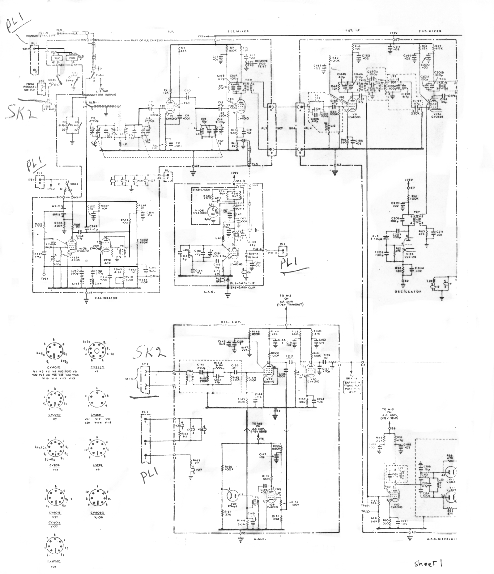
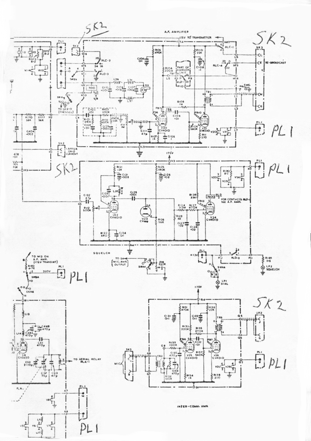 |  |
| RHS of schematic | middle part of schematic |
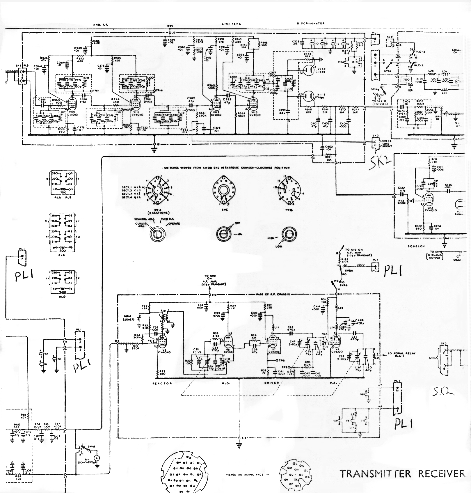
 | 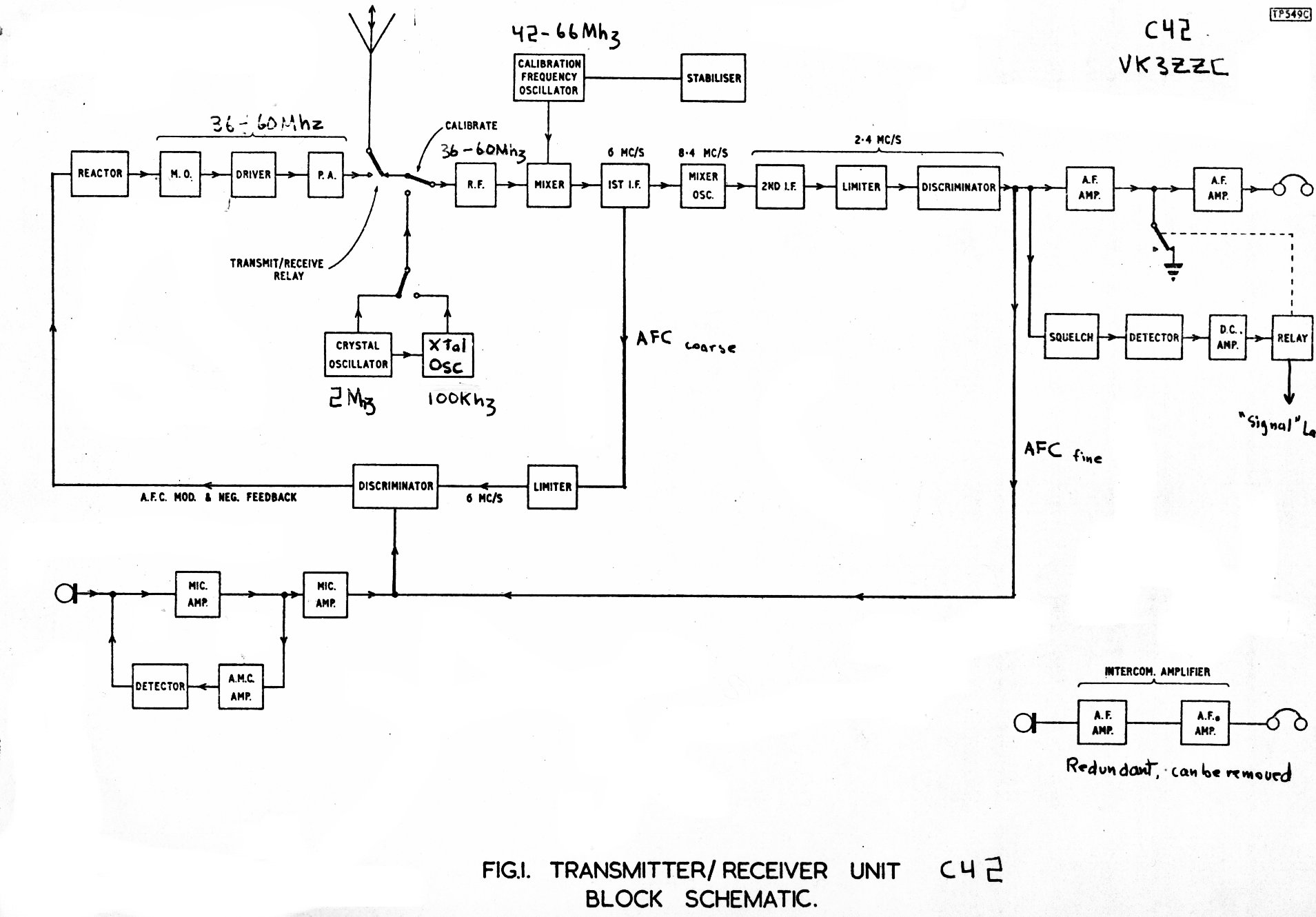 |
| LHS of schematic | general system block diagram |
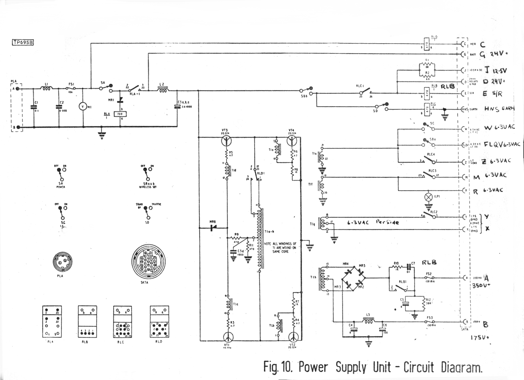 |  |
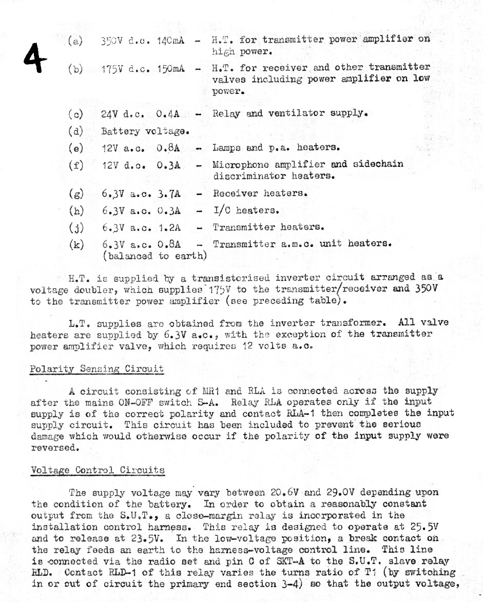
| the seperate power supply unit | C42/45 power requirements |
 |  |
| PSU output pins and voltages | |
 |  |
| |
 |  |
| |
 |  |
| |
 |  |
| |
 |  |
| |
And thats all of the C45/C42 EMER (Electical and Mechanical Engineering Regulations) manual that I possess. The most complete
manual for this and all the Larkspur series radios can now be obtained from royalsignals.org.
I am not allowed to reproduce the royal signals EMERs here. it is well worth the effort to take the time and trouble to register
with
the site and get the download permits and keys. The royal signals
people appear to have available scans from the virgin first
generation documents and their scans and retouching is off the
highest quality.
homepage
you are most welcome to email me at
Thu Jul 17 19:23:25 EST 2008 added repair note, email sig
